Pneumatic Caisson Method Shimizu’s Pneumatic Caisson Projects
Constructing robust underground structures that ensure functionality and stability is essential when building critical infrastructure such as pumping stations, shafts, and road tunnels. The pneumatic caisson method is particularly valuable under challenging conditions, including soft ground and underwater environments, because it provides a safe and reliable means of construction. Shimizu has been involved in numerous large-scale projects using this specialized method over many years, contributing to the development of social infrastructure. This page introduces some of our pneumatic caisson projects and the innovative technologies we have developed and deployed.
What Is the Pneumatic Caisson Method?
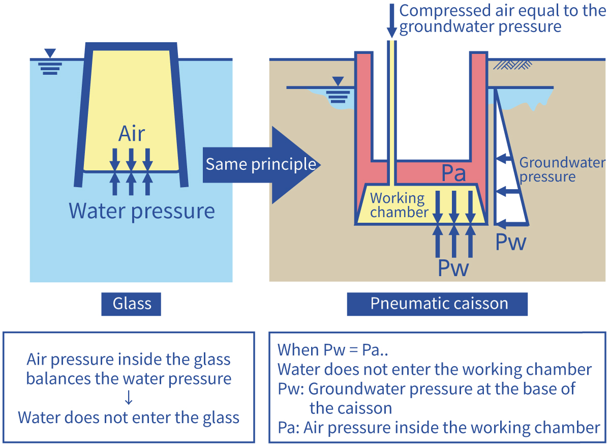
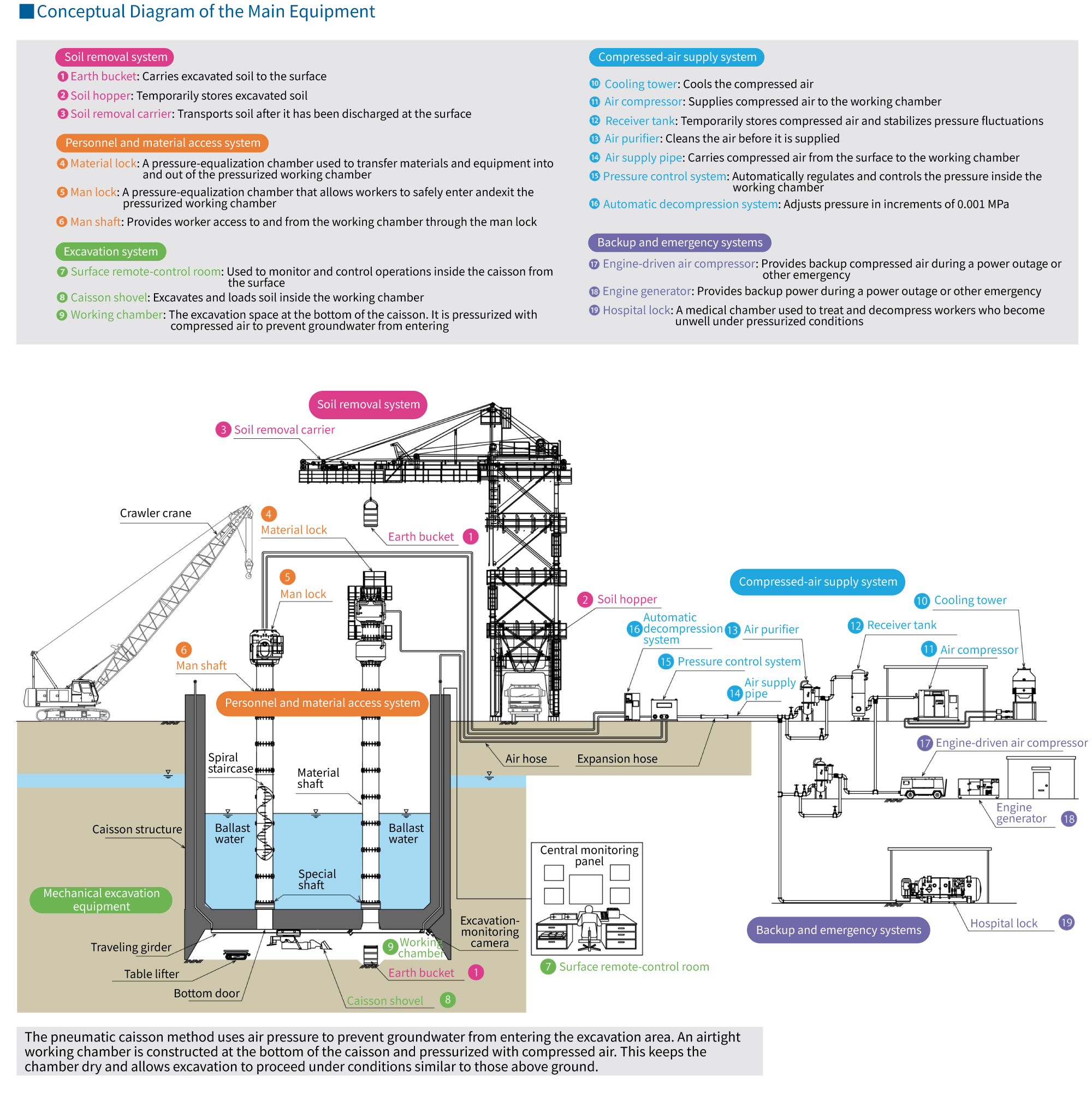
A pneumatic caisson is literally an “air box.” An airtight working chamber is constructed at the bottom of a reinforced-concrete structure built above ground. Compressed air is then supplied to the chamber to prevent groundwater from entering while excavation and soil removal are carried out, allowing the structure to be gradually sunk into the ground.
The method applies the same principle seen when an upside-down glass is pushed into water: the air trapped inside prevents water from entering. As a result, excavation can be performed inside the working chamber at the bottom of the caisson under conditions similar to those above ground.
Continuous Construction Using Multiple Pneumatic Caissons
New Saitama East-West Connector Road between Kita-Yono and Omiya on the Saikyo Line
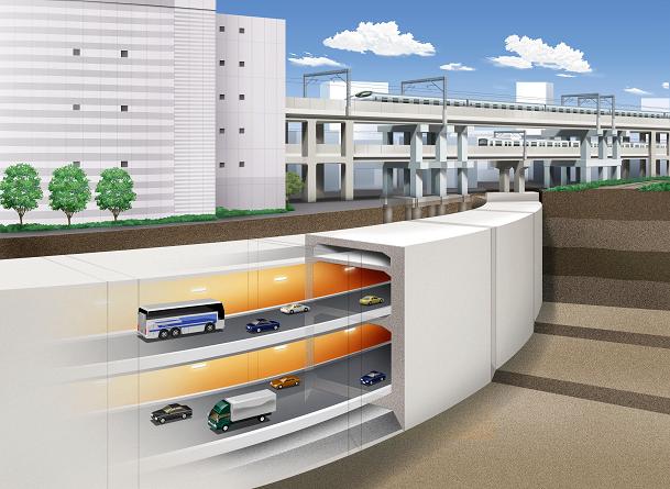
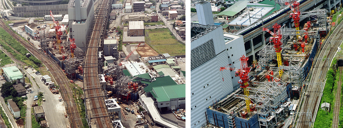
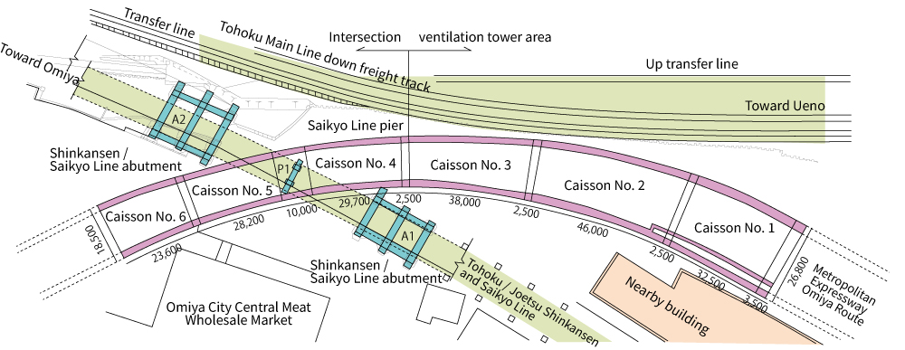
This project formed part of the Omiya Route of the Metropolitan Expressway, which directly connects central Tokyo with Saitama Shintoshin, an important center supporting the functions of Japan’s capital region. The work involved constructing a tunnel beneath the elevated JR East Shinkansen and Saikyo Line tracks. A 221.5-meter road tunnel was constructed as a single integrated structure by sinking six pneumatic caissons in succession.
Constructing a Long Tunnel by Continuously Sinking Multiple Caissons
Six two-level box-culvert caissons were positioned along a curved alignment and sunk in succession within a confined area close to critical infrastructure, including the Shinkansen and Saikyo Line. Despite the curved alignment and complex geological conditions, including soft ground and confined aquifers, sinking accuracy of within ±50 mm both horizontally and vertically was achieved. The work was carefully controlled to maintain groundwater levels and minimize the effects on nearby structures. A gap of approximately 2.5 meters remained between each caisson. These gaps were mechanically excavated and the caissons rigidly connected, creating a single, integrated 221.5-meter road tunnel.
New Saitama East-West Expressway Connector Road between Kita-Yono and Omiya on the Saikyo LineLocation
- Location
- 2-chome Kishikicho to 62 Nishikicho, Saitama City, Saitama Prefecture
- Client
-
Tokyo Construction Office, East Japan Railway Company *Constructed under an agreement with the Metropolitan Expressway Public Corporation - Construction period
- October 1999 – October 2003
- Structure and scale
-
Plan dimensions: 23.6 m × 18.5 m to 46.0 m × 22.2 m Caisson area: 424–1,038 m2; six caissons
Depth: GL −31.5 m to −37.7 m
Construction of the World’s Largest Pneumatic Caisson by Plan Area
Higashiogu Water Reclamation Center Nishi-Nippori Pump Building
The Higashiogu Water Reclamation Center was planned as a sewage and stormwater treatment facility to improve water quality in the Sumida River and prevent eutrophication in Tokyo Bay. Shimizu constructed the Nishi-Nippori pump building.
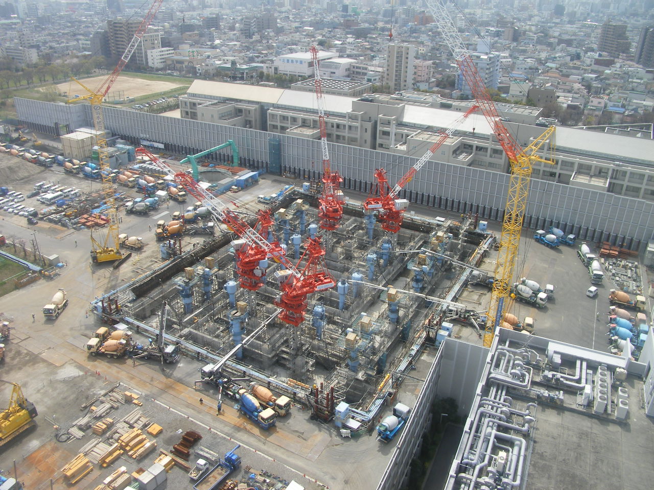
The World’s Largest Pneumatic Caisson by Plan Area
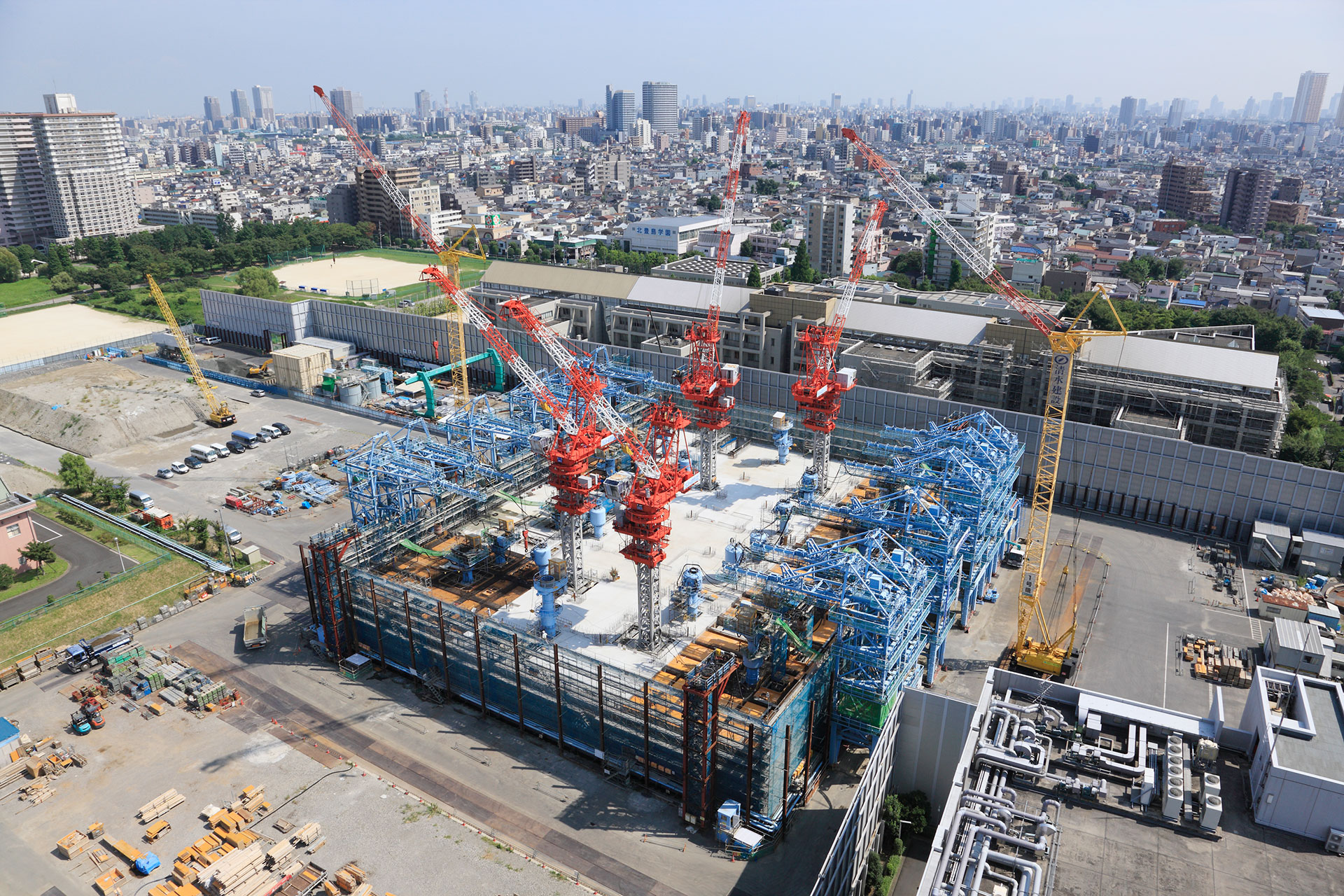
The Nishi-Nippori pump building is a large underground structure with a plan area of 4,838 m2, equivalent to approximately 18 tennis courts, and a depth of 43.9 m below ground level. It was constructed using the world’s largest pneumatic caisson by plan area.
Recipient of the FY2011 JSCE Technical Award
Higashiogu Water Reclamation Center Nishi-Nippori Pump Building
- Location
- 7-2 Higashiogu, Arakawa City, Tokyo
- Client
- First Core Facility Reconstruction Office, Bureau of Sewerage, Tokyo Metropolitan Government
- Construction period
- September 2006 – February 2011
- Structure and scale
-
Plan dimensions: 62.1 m × 77.9 m Area: approximately 4,838 m2
Depth: GL −43.9 m
Construction of a Deep Shield-Tunnel Launch Shaft Using a Pneumatic Caisson
Tokyo Outer Ring Road Tomei JCT and Mainline Shield Tunnel Shaft
The pneumatic caisson method was used to construct the launch shaft that served as the base for mainline shield tunneling on the Tokyo Outer Ring Road between the Kan-Etsu and Tomei expressways.
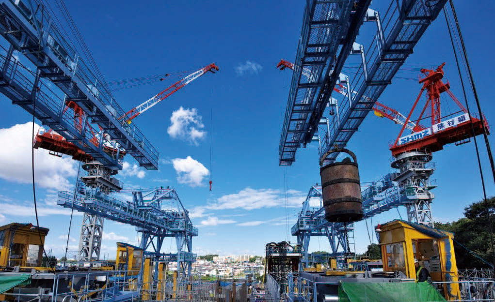
Japan’s Third-Deepest Shield Shaft at the Time of Construction
The caisson was sunk to a depth of 70.3 m below ground level. At the time of construction, this was the third-deepest pneumatic caisson in Japan and, as of December 2025, it ranks fourth. It was also Shimizu’s deepest pneumatic caisson project at the time and involved the highest working pressure the Company had used, reaching a maximum of 0.462 MPa.
Three-Dimensional Design Eliminating the Frame Beam
A reinforcing beam is normally installed above the shield opening in a launch shaft. Before construction, however, the design was revised using three-dimensional FEM analysis, allowing this frame beam to be eliminated. Removing the beam increased the available interior space and improved the efficiency and constructability of the shield tunneling work.
*Frame beam: A beam installed in a shaft wall to reinforce the opening through which a shield machine is launched or received. It resists stresses from the machine’s thrust, earth pressure, and other loads, helping to ensure the stability of the shaft as a whole.
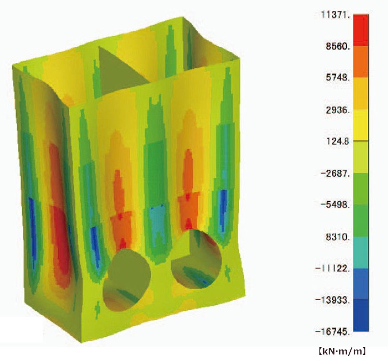
(Horizontal bending-moment diagram after formation of the shield opening)
Grid-Pattern SEW Method for a Large-Diameter Shield Opening
The SEW method*1 (developed by another company) was used at the opening so that the shield machine could cut through it smoothly during launch.
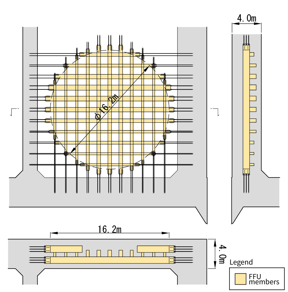
The opening had a large diameter of 16.2 m and was located approximately 60 m underground, resulting in substantial loads. FFU members*2, which are normally installed in only one direction, were therefore arranged in a grid and integrated with the concrete to increase structural strength. This was the first use in the industry of a composite structure that combines grid-arranged FFU members with concrete.
*1 SEW method: A method developed by The Zenitaka Corporation and Sekisui Chemical Co., Ltd. FFU members are incorporated into the section of an earth-retaining wall through which the shield machine will pass, enabling the machine to cut directly through the wall.
*2 FFU (Fiber Reinforced Foamed Urethane): A fiber-reinforced foamed urethane material formed into rectangular structural members by adhesive lamination.
Tokyo Outer Ring Road Tomei JCT and Mainline Shield Tunnel Shaft
- Location
- Okura, Setagaya City, Tokyo
- Client
- Tokyo Branch, Central Nippon Expressway Company Limited
- Construction period
- September 2012 – September 2015
- Structure and scale:
-
Plan dimensions: 48.2 m × 28.1 m Area: 1,354 m2
Depth: GL −70.3 m
Construction of an Underground Library Using the Pneumatic Caisson Method
University of Tokyo General Library Annex
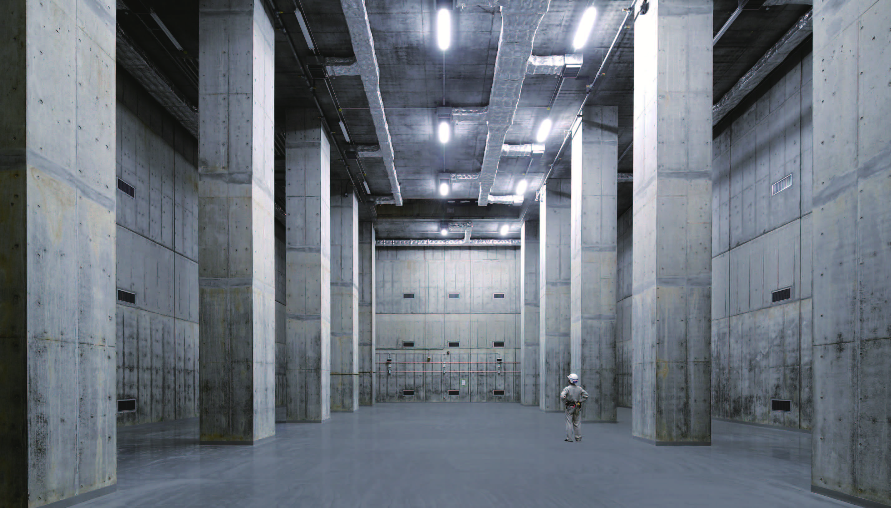
To enhance the functions and expand the storage capacity of the General Library at the University of Tokyo’s Hongo Campus, Shimizu constructed an underground library equipped with an automated storage system capable of accommodating three million additional books. The existing General Library holds approximately 1.2 million books.
To preserve the campus landscape, the new facility was constructed beneath the fountain plaza in front of the existing library. Basement floors 2 through 4 contain the automated storage system, while basement floor 1 is used as a study area.
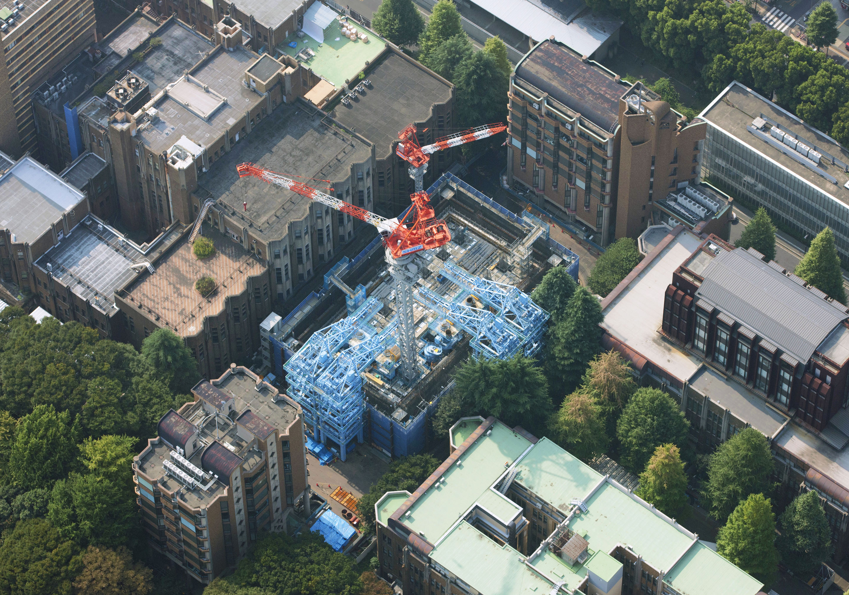
Confined Construction Area Surrounded by University Buildings
Construction was carried out under difficult conditions, with existing university buildings surrounding the site on all four sides. To minimize effects on the surrounding structures, steel sheet piles were installed to separate the caisson from the adjoining ground while also serving as earth-retaining walls. A friction-reducing material was also used around the caisson during sinking. Before work began, two-dimensional FEM analysis was performed to verify the effectiveness of these measures.
Water-Stop Steel Plates Covering the Entire Exterior Wall
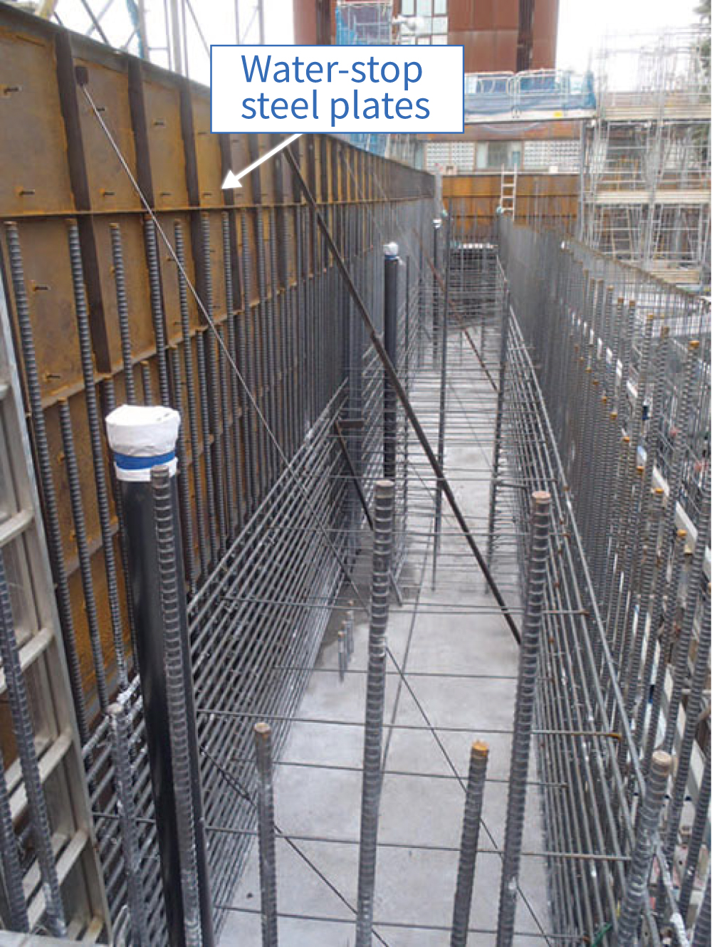
Because book storage areas must be protected from moisture, 6 mm-thick water-stop steel plates were installed over the outer surfaces of the exterior concrete walls and used as permanent formwork. The entire structure, including the cutting edge and bottom slab, was covered with steel plates to reliably prevent groundwater infiltration.
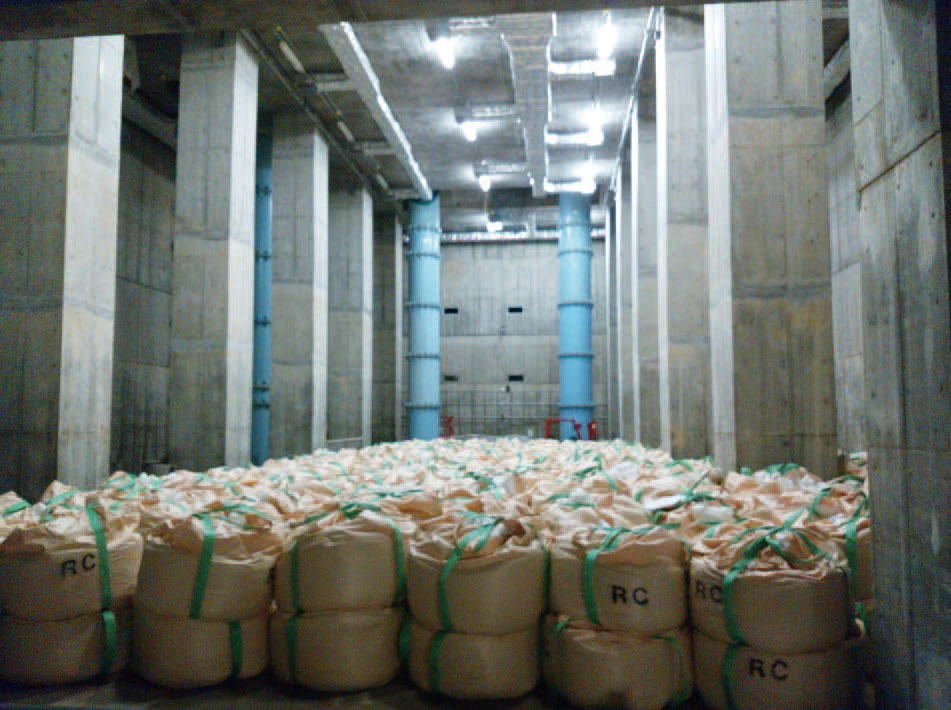
Promoting Sinking with Large Sandbags
The structure requires sufficient downward force from its own weight to sink. When the structure alone is not heavy enough, water is normally stored inside it to increase its weight. Because the completed structure would be used as a book storage facility, water was not used in this project. Instead, large sandbags and similar weights were placed inside to promote sinking.
University of Tokyo General Library Annex
- Location
- Hongo, Bunkyo City, Tokyo
- Client
- The University of Tokyo, National University Corporation
- Construction period
- November 2014 – May 2017
- Structure and scale
-
Plan dimensions: 44.2 m × 26.6 m Area: 1,176 m2
Depth: GL −46.3 m
Construction of One of Japan’s Largest and Deepest Pneumatic Caissons for a Pumping Station
Nagoya City Hirokawa Pumping Station
The Hirokawa Pumping Station is a stormwater drainage facility built to improve flood protection around Nagoya Station. It discharges rainwater from the upper Nakagawa Canal area and surrounding districts into the canal.
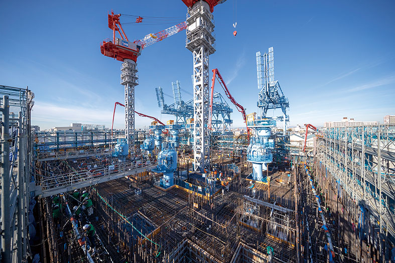
Japan’s Deepest Pneumatic Caisson Construction for a Pumping Station under High Air Pressure
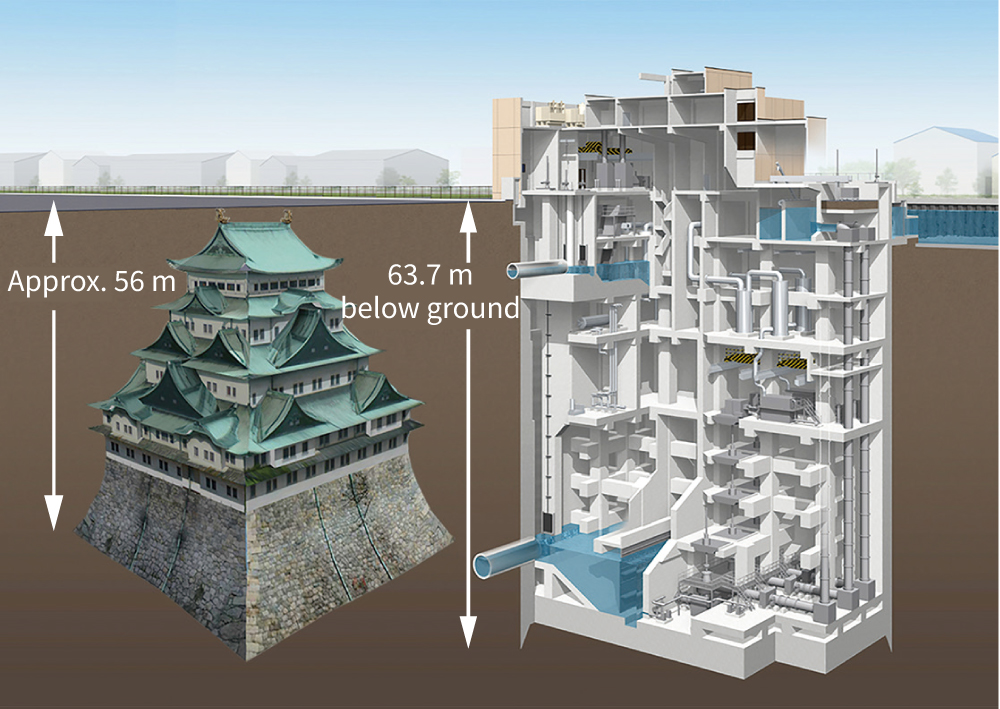
The pumping station structure, measuring 52.0 m × 29.5 m in plan, approximately 1,530 m2 in area, and 63.7 m in depth below ground level, was constructed using the pneumatic caisson method. It is the deepest pumping station in Japan constructed by this method and is deep enough to accommodate the entire approximately 56-meter height of Nagoya Castle. Because pressure in the working chamber at the bottom of the caisson reached 0.62 MPa, equivalent to 6.2 atmospheres, excavation was performed remotely without workers inside the chamber.
Shortening the Schedule by Postponing Internal Structure Construction
In a large pneumatic caisson project, sinking and excavation are normally carried out in parallel with construction of the exterior walls, slabs, and interior walls. For this project, the construction sequence was studied in detail using three-dimensional finite element analysis. The analysis verified, prior to construction, that reinforcing the exterior walls and beams would allow the exterior walls alone to withstand earth and water pressure, without requiring the interior walls or slabs to be reinforced. Based on this finding, the slabs and interior walls, which would otherwise have had a major effect on the overall schedule, were constructed after excavation was completed. This significantly shortened the construction period.
Nagoya City Hirokawa Pumping Station Construction No. 2
- Location
- Hirokawacho, Nakagawa Ward, Nagoya City
- Client
- Japan Sewage Works Agency (Project owner: Nagoya City Waterworks and Sewerage Bureau)
- Construction period
- November 2015 – May 2022
- Structure and scale
-
Plan dimensions: 52.0 m × 29.5 m Area: approximately 1,530 m2
Depth: GL −63.7 m
Construction of a Convex Pneumatic Caisson with One of the World’s Longest Sides
Reconstruction of the Ishinomaki Chuo Drainage Pumping Station and One Other Facility
Stormwater drainage facilities and a main box culvert were constructed in central Ishinomaki, where ground subsidence caused by the Great East Japan Earthquake had created a need for additional flood-control measures.
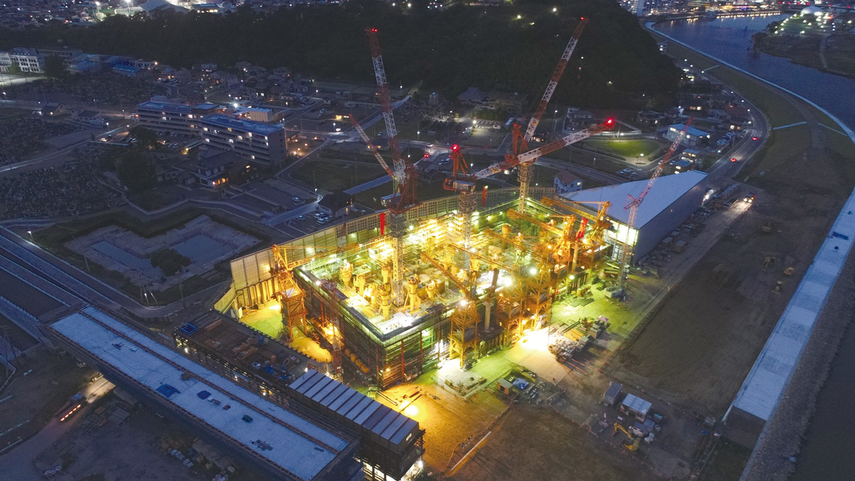
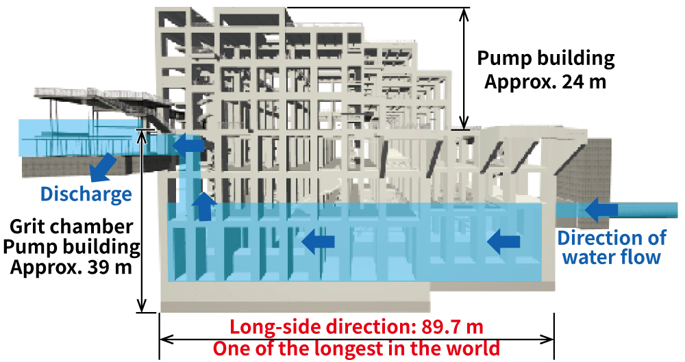
Convex Plan Shape with Japan’s Longest Side, Measuring 89.7 m
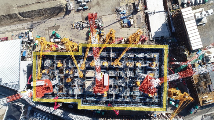
The stormwater pumping station structure measures 89.7 m × 41.2 m in plan and has an overall depth of approximately 39 m, comprising a depth of 35.3 m below ground level plus the aboveground civil-engineering portion, and was constructed using the pneumatic caisson method. Because the structure had a convex plan shape, special care was required to prevent stress concentrations during sinking from damaging the corners along its long side. At 89.7 m, the long side is the longest in Japan for a structure constructed using the pneumatic caisson method.
Pneumatic-Caisson Version of SP-MAPS
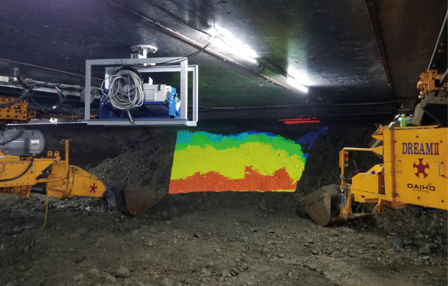
To ensure that a pneumatic caisson remains stable as it sinks, excavation is performed while portions of soil immediately inside the cutting edge are temporarily left in place.
For this project, Shimizu applied the pneumatic-caisson version of SP-MAPS, a system that visualizes excavation progress in these unexcavated areas around the cutting edge. The project confirmed the effectiveness of the system.
Recipient of the FY2023 JSCE Technical Award
Reconstruction of the Ishinomaki Chuo Drainage Pumping Station and One Other Facility, Parts 2 and 3
- Location
- Ishinomaki City, Miyagi Prefecture
- Client
- Japan Sewage Works Agency (Project owner: Ishinomaki City)
- Construction period
- February 2018 – March 2023
*External works continued through July 2023 - Structure and scale
-
Plan dimensions: 89.7 m × 41.2 m Area: 3,362 m2
Depth: GL −35.3 m
Deeper, Larger, and More Precise. Shimizu’s Pneumatic Caissons
Shimizu has completed 29 pneumatic caisson projects since 2000.
Safe and Reliable Construction of Social Infrastructure Using Pneumatic Caissons
The pneumatic caisson method makes it possible to safely and reliably construct underground structures without temporary earth-retaining walls, even in environments with high groundwater levels or in marine and river locations. The method contributes significantly to the construction of social infrastructure, including water and sewerage facilities and bridge foundations. Including the projects presented here, Shimizu has an extensive track record encompassing approximately 90 caissons. Applications have ranged from pier foundations and pumping stations to tunnel shafts and an underground library. The Company has also completed projects outside Japan, including in Vietnam and Bangladesh. Shimizu has continued to embrace new approaches, including the use of DX technologies such as SP-MAPS to improve structural construction accuracy, highly accurate prediction of surrounding-ground displacement using particle methods, and shorter construction periods achieved through innovative construction sequencing. We will continue striving to provide value that exceeds the expectations of society and our clients while contributing to the development of social infrastructure.
The information posted here is the current information on June 23, 2026.
Please be aware that this information may have changed by the time you view it.