
Smart Innovation Ecosystem Novare
(The Future of Monozukuri with 3D Printers)
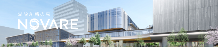
Novare: A new platform that creates next generation innovation
Novare is an open innovation hub nestled in Shiomi, Koto-ku, Tokyo. Its name, derived from the Latin word for “to create” or “to renew,” embodies its purpose—to create a place for new invention by bringing together knowledge from Japan and overseas. Comprised by five facilities which work both independently and collaboratively, Novare mirrors the intricate ecosystems of nature, all converging at the heart of monozukuri (superb craftsmanship).
- Project site
- Shiomi, Koto-ku, Tokyo
- Site area
- 32,233.97 m²
- Stage
- Complete (2023)
Pursuing the future of monozukuri with new processes for reducing labor, materials, and environmental impact
Shimizu celebrated its 220th anniversary in November 2023. Novare’s mission is to inherit the DNA of knowledge, technology, and human resources cultivated over the long history and tie it into innovations.
The five facilities that comprise Novare work both independently and collaboratively, bringing together knowledge from Japan and overseas to create a place for new invention. In other words, it is also a place where various new technologies are introduced in field trials.
The facilities have taken on the challenge of monozukuri (superb craftsmanship) with new processes that reduce labor, materials, and environmental impact, aligning with modern societal circumstances and environmental needs. Here, we introduce three examples of future monozukuri that make use of 3D printers in different ways.
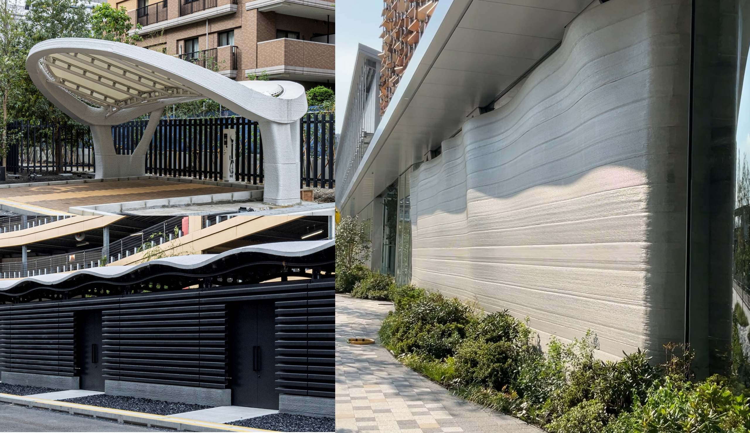
Environmentally friendly 3D curved wall formwork using 3D printer
One of the features of 3D printers is that they can easily create free-form shapes and excel in customized production. Leveraging this feature, The project team took on the challenge of developing environmentally friendly 3D curved wall formwork.
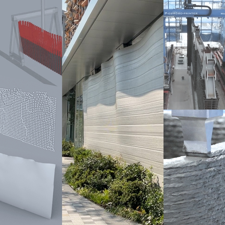
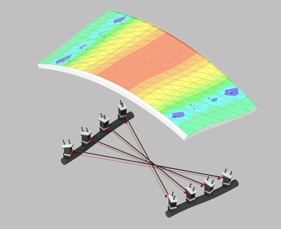
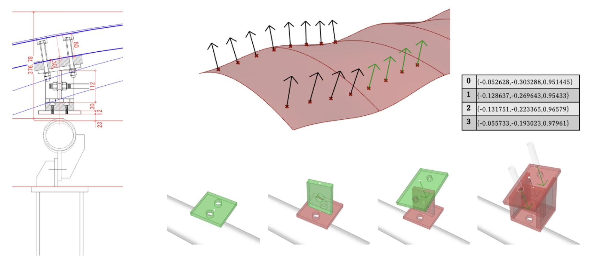
First, stress distributions were generated for long-term loads and earthquake loads using FEM analysis to calculate the shear force that determines the thickness of the wall (figure on the right).
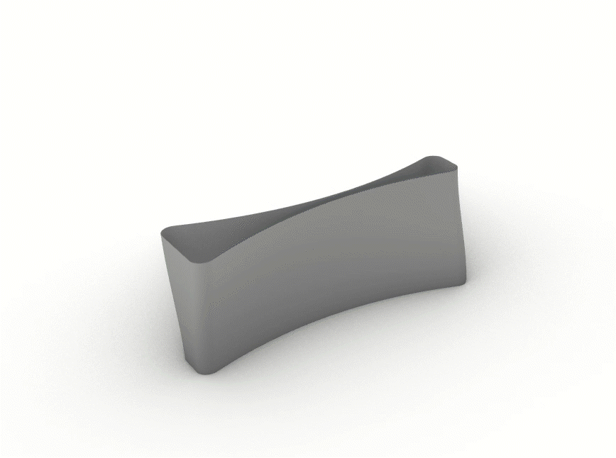
The thickness is determined based on the stress distribution image data, and a shape is created by eliminating parts that are not structurally necessary. By thickening the wall where necessary and slimming it down everywhere else, concrete usage was successfully reduced by 10% (figure below).
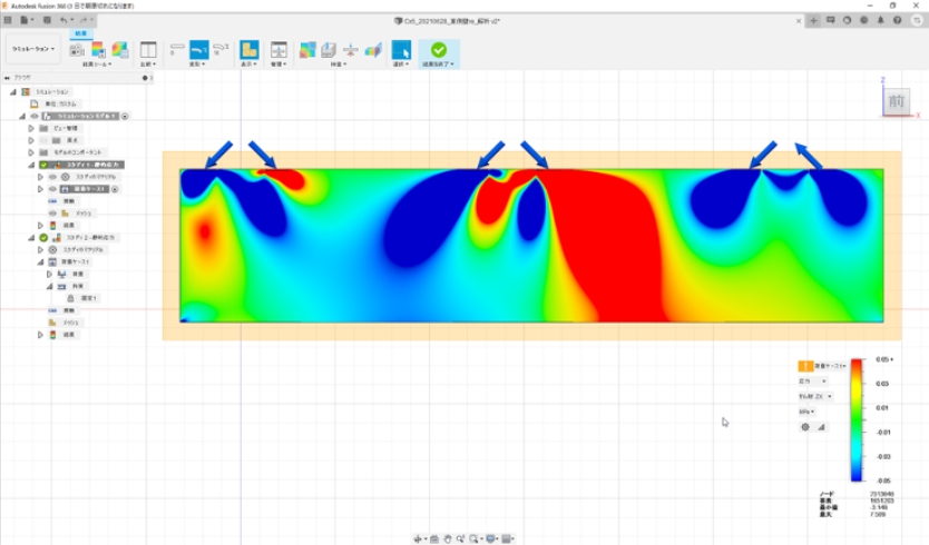
Stress diagram of the dominant shear force. Red indicates a positive direction, blue indicates a negative direction, and the arrow indicates the position of the truss leg.
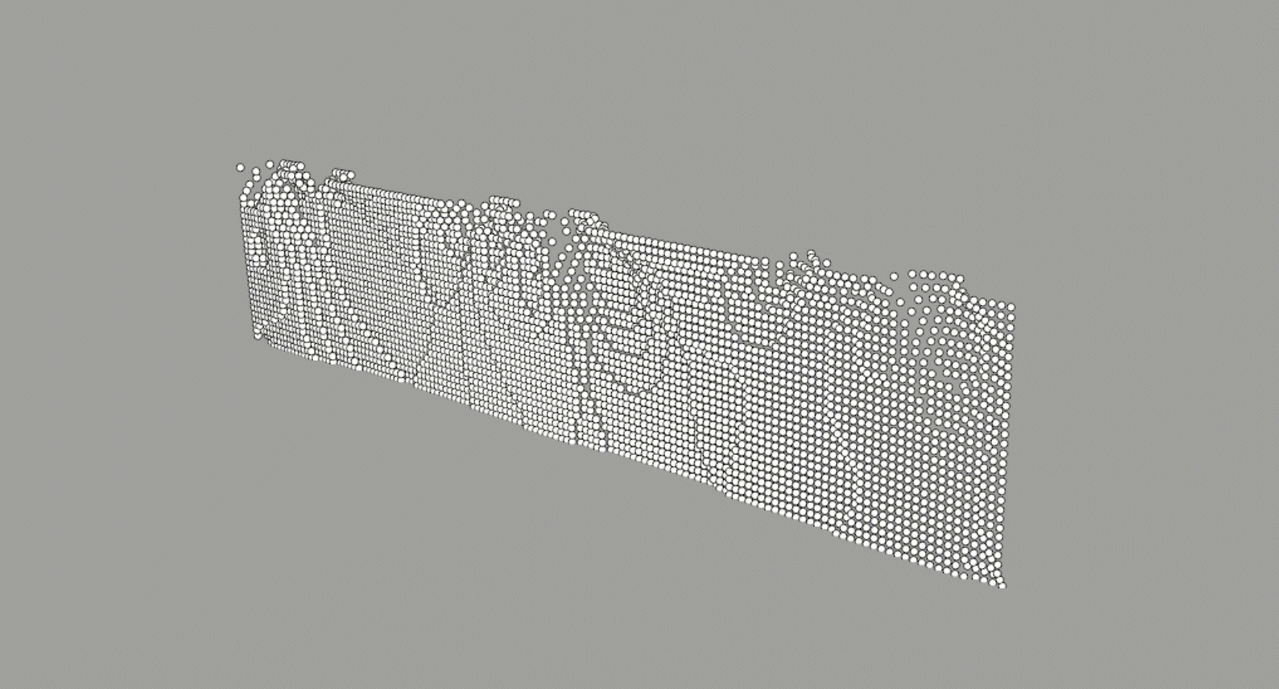
The stress distribution diagram is converted to wall thickness. By making it smooth, the amount of concrete was ultimately reduced by 10%.
Print simulation using 3D data
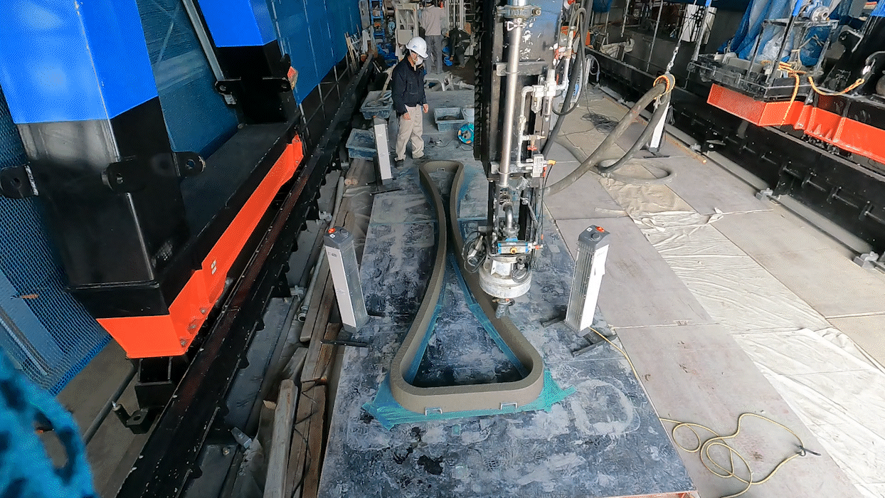
Next, the print was simulated in Grasshopper. This process uses 3D data to digitally verify information, such as how long it will take to print and how much material will be required. 3D printing involves more than just sending data; it also requires programming to operate the machine. This time, writing out a G-CODE program directly in Grasshopper allowed to link design and construction easily.
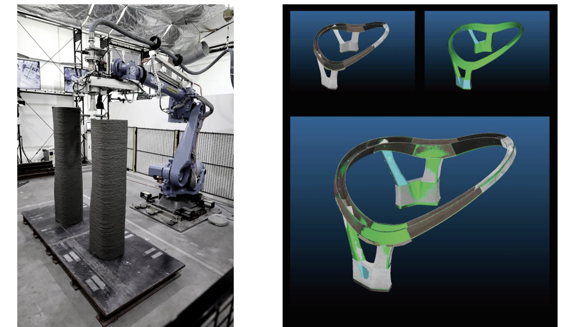
It was a vast wall measuring 20 m long and 4.5 m high. Therefore, on-site printing was implemented. This was the first time for the project team to try digital fabrication, which involves 3D printing on site based on design data. It was completed in about two weeks, printing four to five hours daily. The various information obtained, such as on mixing materials according to temperature, will be valuable data for future 3D printing construction.
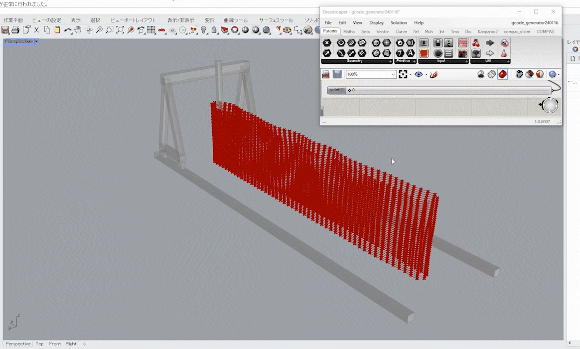
Performing simulation in Grasshopper and centrally managing information necessary for construction
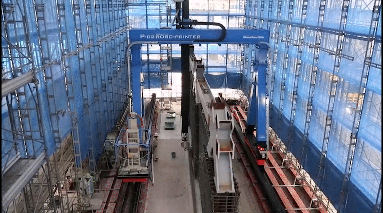
Shimz Robo-Printer is a construction 3D printer that can directly print full-scale structures at the construction site.
Even massive objects can be printed seamlessly on site.
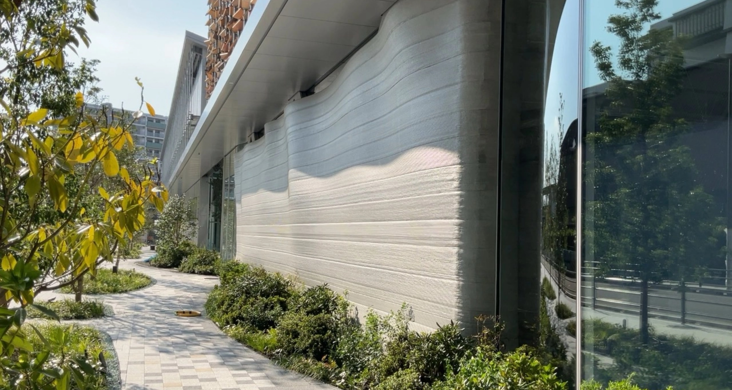
Reducing CO2 emissions by 60% using environmentally friendly materials
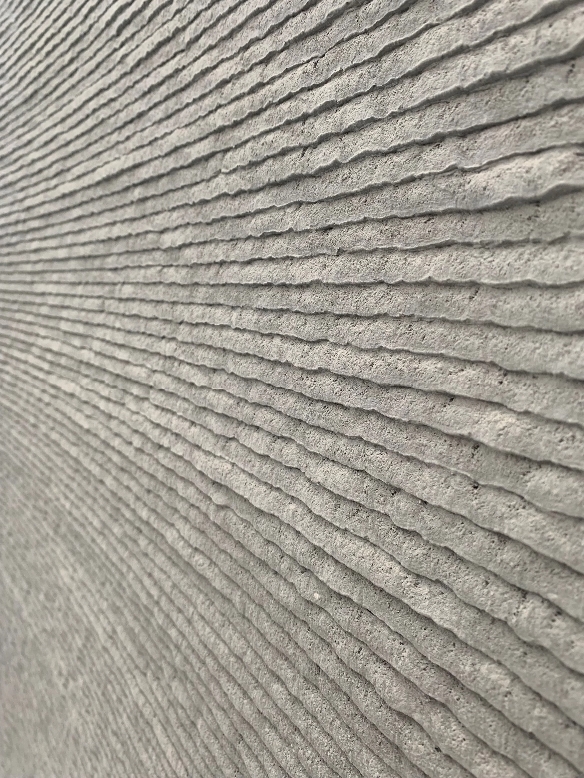
Here, an automatic plasterer where a brush is attached to the nozzle of a 3D printer was incorporated to create textures. After testing various sponges and animal furs, goat hair was selected. The result was a wall with a unique wavy appearance.
In addition, the 3D curved wall formwork is made with ECM concrete, a low-carbon concrete developed by another company, which contains a large amount of blast furnace slag powder. This large amount of blast furnace slag powder means ECM neutralizes faster than ordinary concrete, and thereby not suited for use in places exposed to fresh air. However, the material used in 3D printers is very dense and impervious to both water and air, which allows for the full utilization of ECM concrete’s advantages. This is a new initiative unique to the open innovation facilities to combine products from competing companies with in-house technology to address the social issue of reducing CO2 emissions.
It is an environmentally friendly wall that reduces the amount of concrete used and cuts CO2 emissions by 60% compared to conventional materials, with no waste from the formwork.
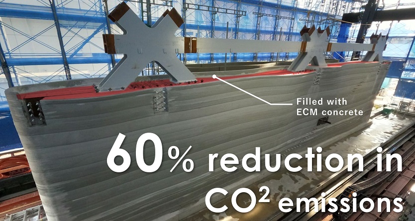
With ECM concrete, 60-70% of the cement is replaced with blast furnace slag powder, a byproduct of steel manufacturing.
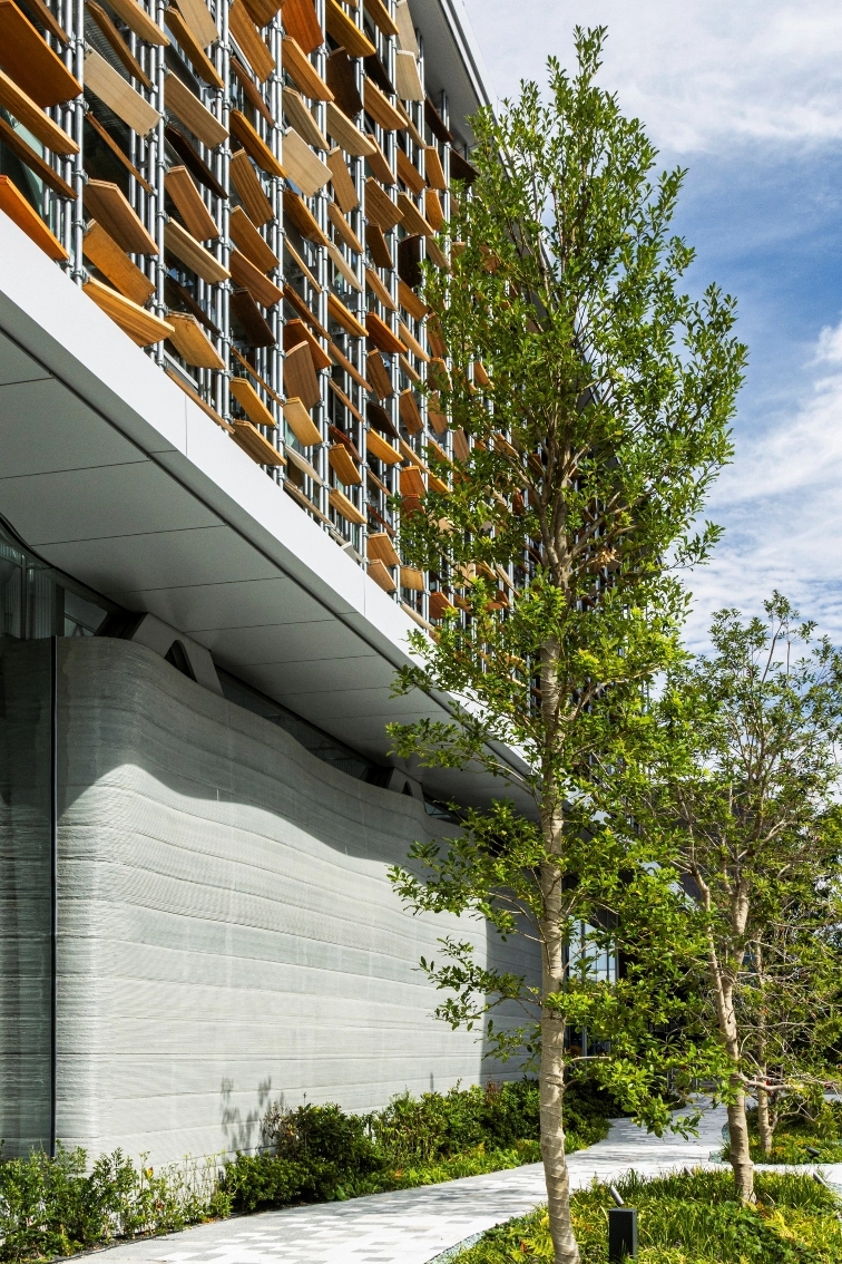
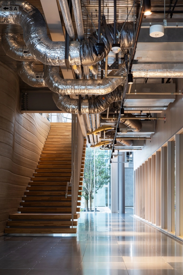
The exterior and interior of a 3D curved wall. The width of each stair has been adjusted to fit along the curved surface of the wall.
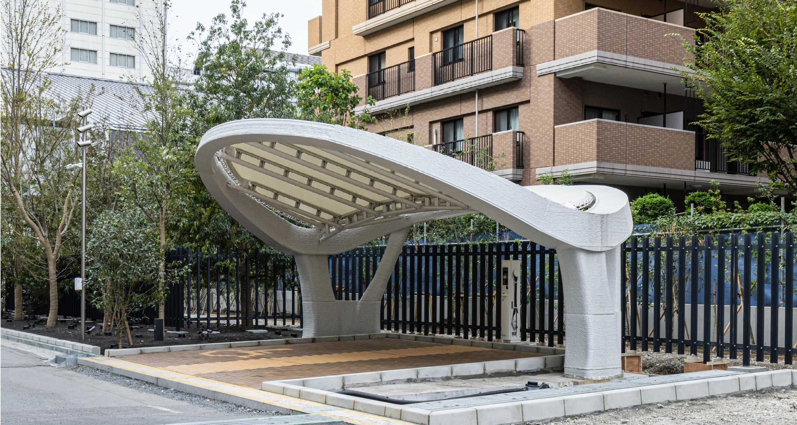
Structural printing to output the parking space itself with a 3D printer
First example in Japan of a 3D printer creating the structure itself
The application of 3D printers in construction is still in its infancy. To expand the possibilities, the challenge of printing the structural elements that form the framework of the building rather than the formwork for concrete was met.
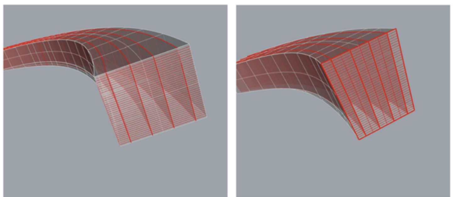
Creating the structure itself with a 3D printer means the methods shown in the figure below in the center and on the right. One of the advantages of creating a structure itself is that it uses fewer materials by incorporating the 3D printed parts as structural elements, consequently leading to reduced environmental impact and improved aesthetic appeal. In addition, printing the structure directly from the design data makes it possible to skip steps such as creating construction and production drawings and placing concrete. Therefore, alongside this project, LACTM (Laminatable Cement-based Tough Material) S, a 3D printer material that can be used as cast-in place concrete, was developed, and ministerial certification was successfully obtained. This was a first in Japan.
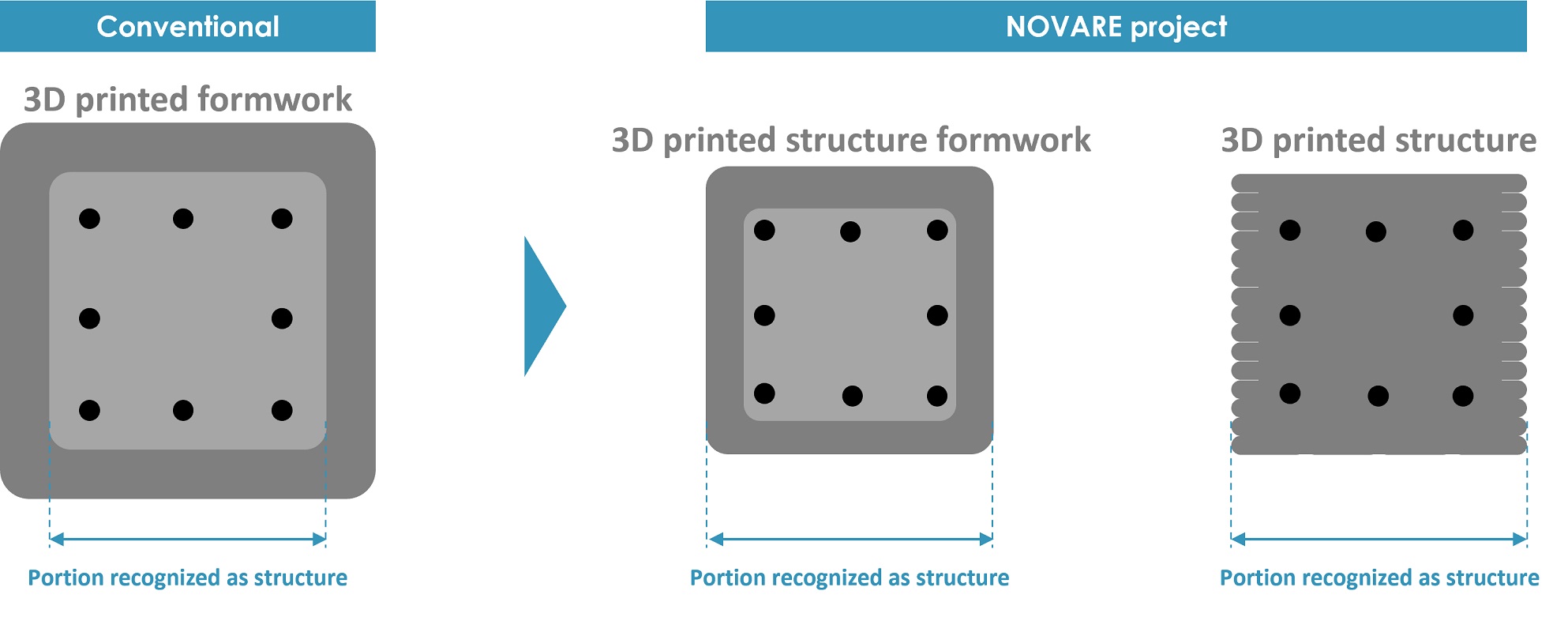
Left: Example of a conventional use case where the dark gray area is created using a 3D printer. Only the light gray area is recognized as a structural element.
Center: The dark gray area is 3D printed structure formwork also recognized as a structural element.
Right: 3D printed structure made by 3D printing and placing rebar inside.
3D design of the optimal structure for the building’s shape
The parking space design makes use of the characteristics of concrete, a compressed material, to incorporate two arches. The long-term load is basically supported by two reinforced concrete pillars, with the stability improved by the supporting pillars. LACTM S, which can be included in the structural calculations, was applied to the arch tips and supporting pillars of the areas desired to be slender in terms of design and structure.
One of the major advantages of 3D printers is that they can print data as-is, making it possible to easily create complex shapes. Various studies were conducted on a design to incorporate 2 arches, and the options were narrowed down to a final proposal.
In addition, the data was created by dividing it into 14 parts, taking into account the parts that would be used as structural elements and the order of construction. This is a data structure unique to digital fabrication, where the data entered is output as-is.
A study of various patterns by analyzing geometrically complex shapes in three dimensions
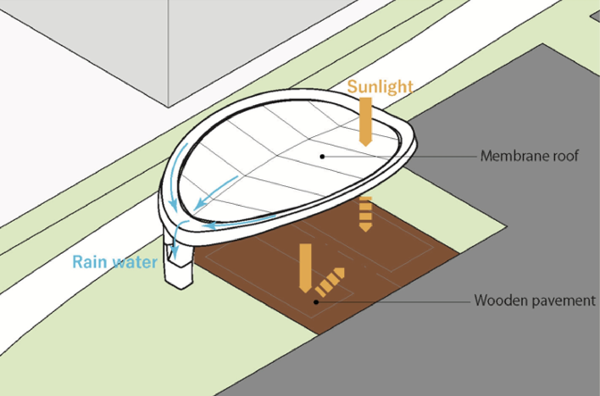
A practical design blocking sunlight and enabling efficient water drainage through 2 rainwater collection points on the roof. The pavement utilizes wood bricks that do not absorb heat.
Utilizing 3D data to test, print, and verify
The gradually changing cross-sections of the components presented a challenge when printing the design. Therefore, the cross-sectional shape was adjusted by controlling the print volume and print speed. The optimal number of print rows was investigated for the cross-sectional change amount.
A process in which test prints are repeated and data is modified according to the print results was introduced to determine the print path. Data was also accumulated as the test prints were conducted.
The test results were reflected in the 3D model, and the print path was determined.
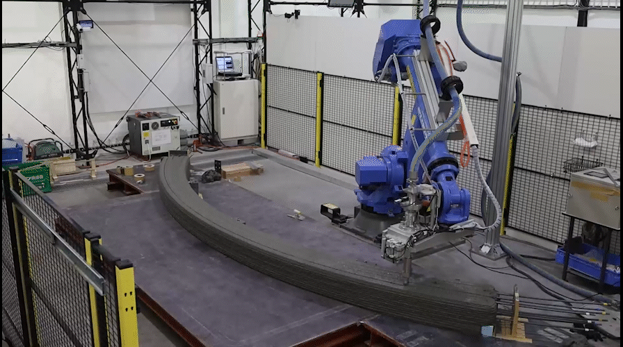
A 3D printing robotic arm was used to print on top of the steel bars to fabricate the components.
In addition, when actually using a 3D printer, the construction site team must manage the 3D data printing. Accordingly, the key points needed to be managed were identified from the 3D data.
The finished components were 3D scanned and superimposed on the model to ensure that the data was as designed. The quality control points, including the accuracy of the printed components and whether there were any errors in the data and figures, were also checked.
Rather than the conventional use of 3D printers, which has been limited primarily to replacing formwork materials, a parking space that uses 3D printing in its structure was created. This project could be called the first step towards the near future, where robots will make all buildings.
Key points to be managed on the print identified from the 3D data
3D scanning printed components and superimposing them on the model for verification
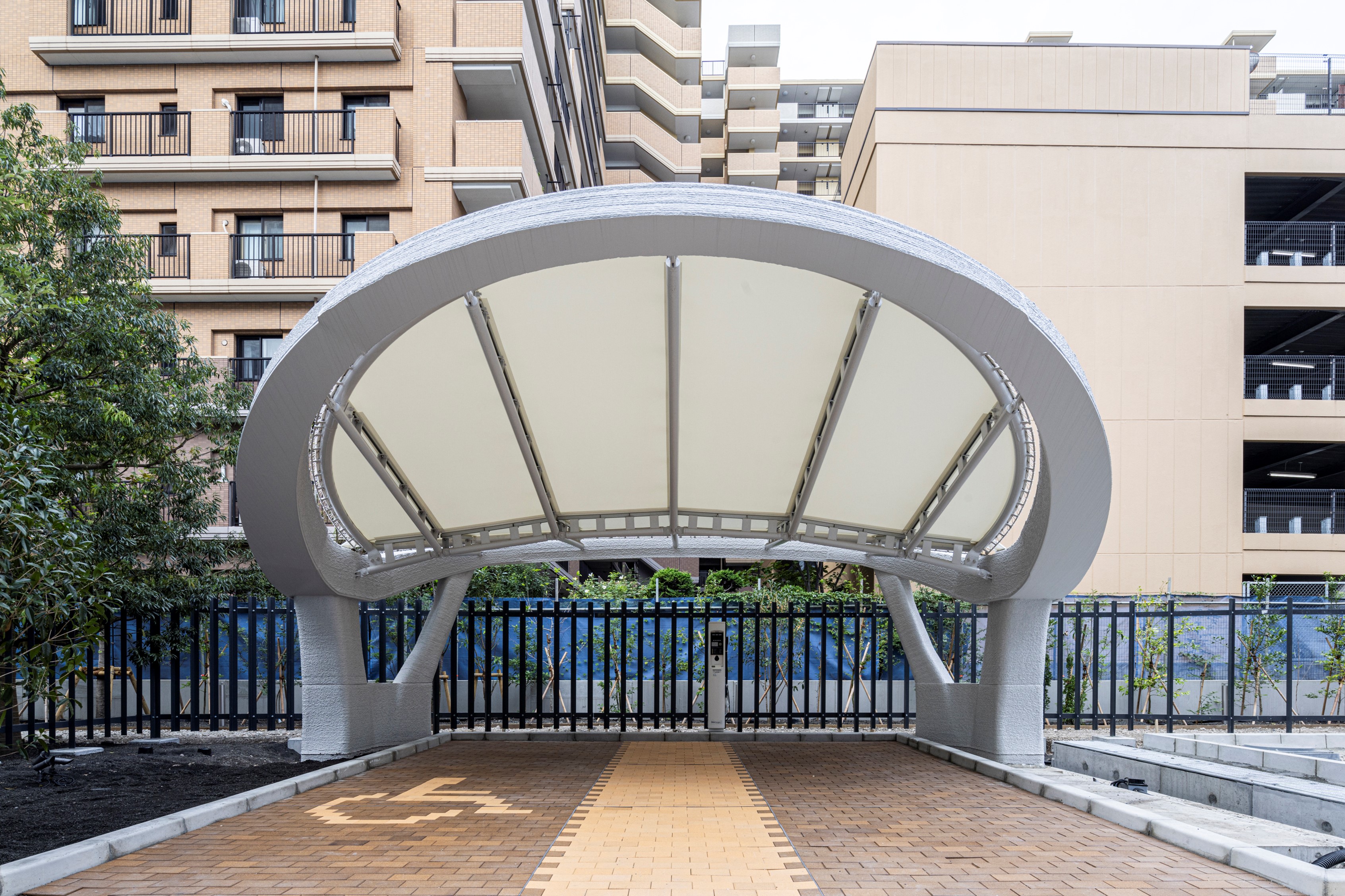
Front of the parking space. The right side is for electric vehicles, and the left side is an accessible parking space.
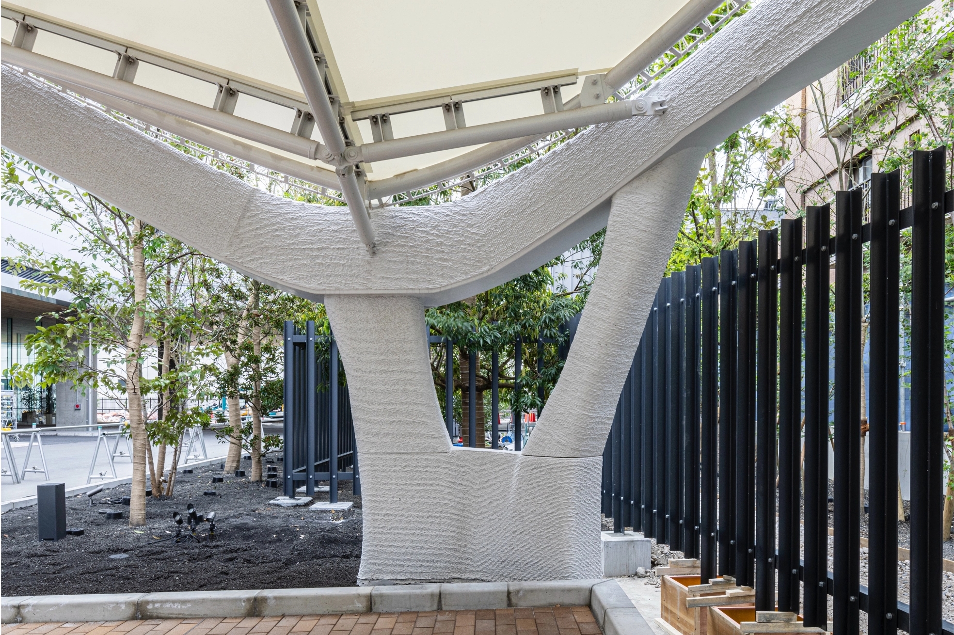
The component's surface has a detailed design with a height of 7 mm.
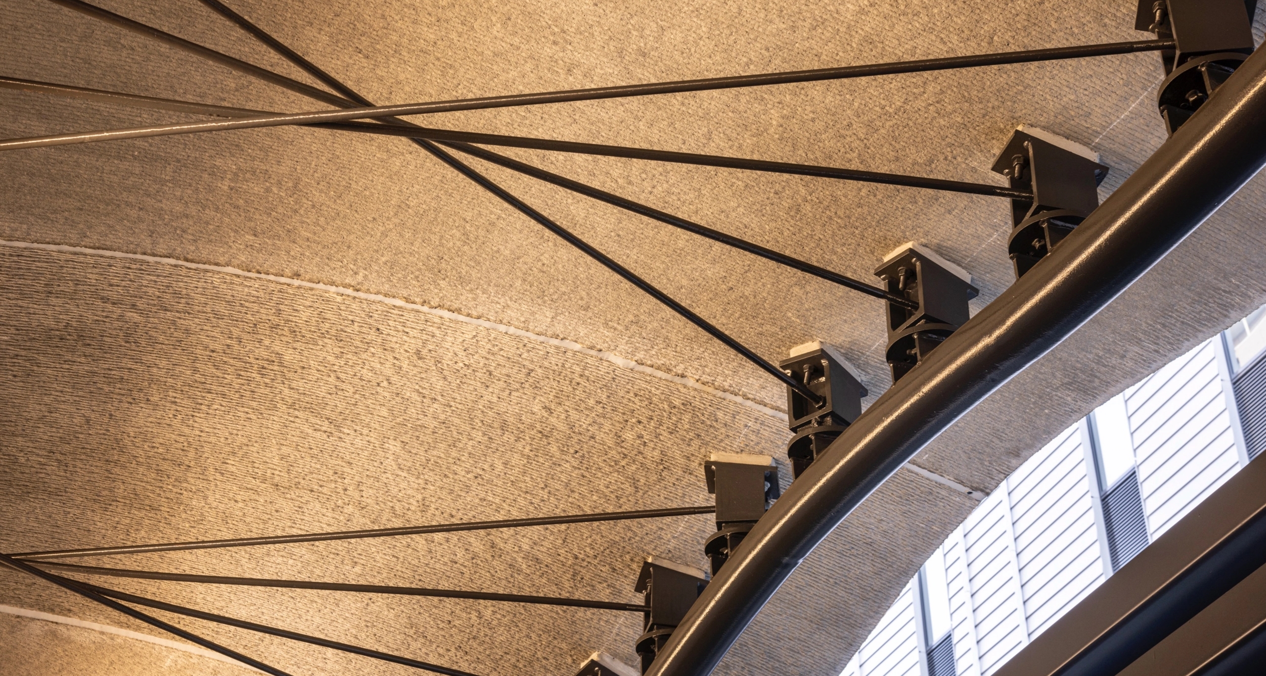
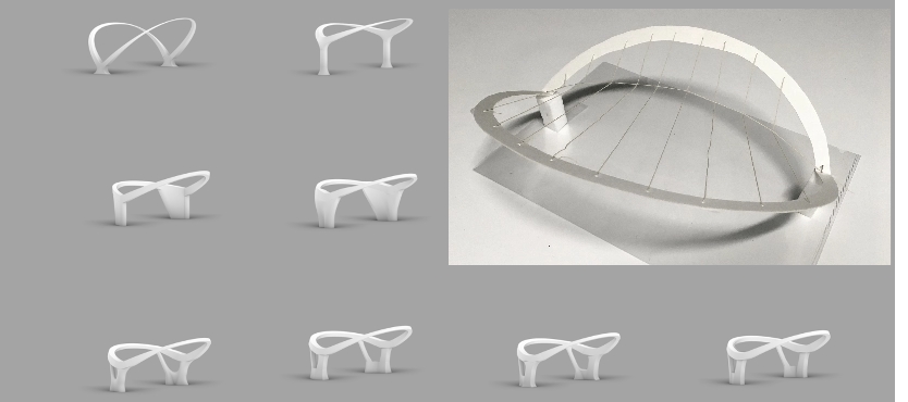
Achieving a 3D wavy roof with shell structure printing
Designing a structure-only building
The challenge of printing a shell structure was taken up as a way to further utilize 3D printing. Specifically, it was a non-reinforced print of exterior finishing materials (roofing materials).
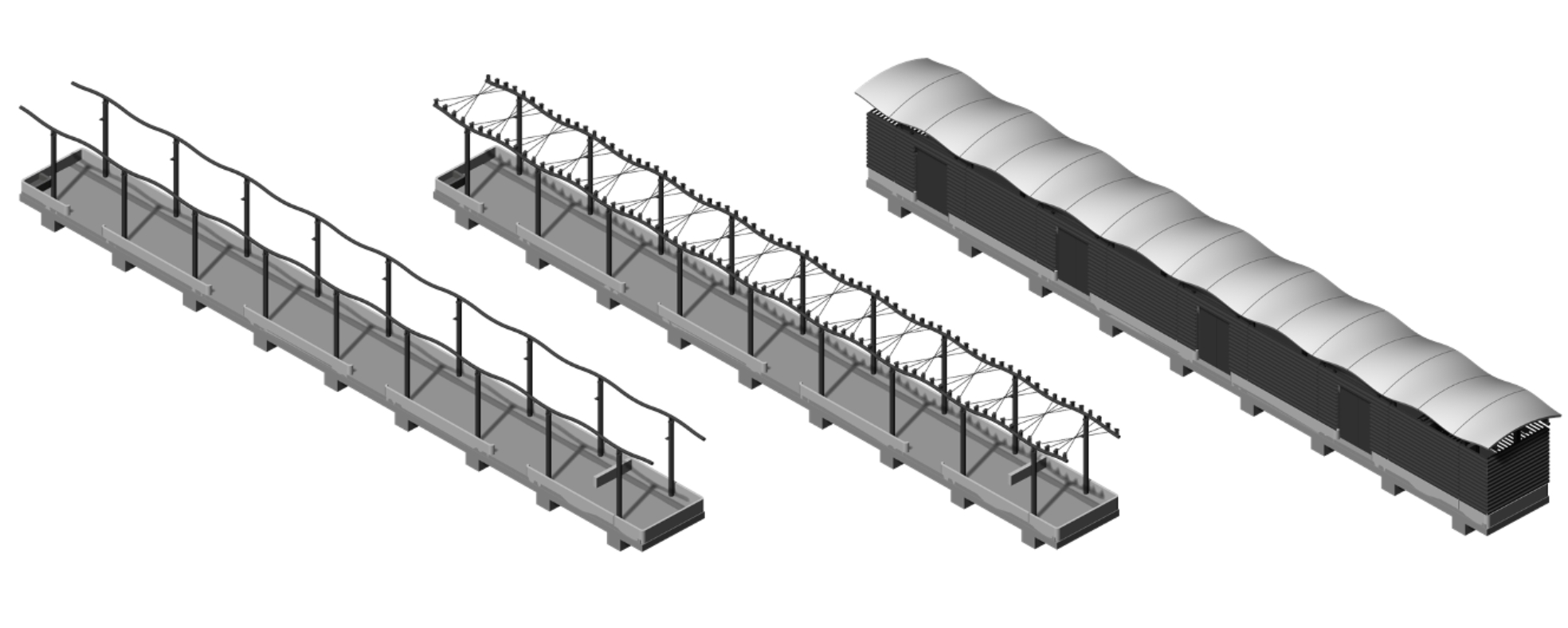
The project started with verifying the design of the structural materials for a semi-outdoor, structure-only building. First, when looking into the combination of a 3D curved surface and a roof, the idea of having a wavy roof came up. With that idea, a roof was designed featuring rods that intersect in the plane and a 3D curved surface using sine curves with the long side beams being shifted by half a phase.
The rise of the roof was then reduced to preserve an unconstrained horizontality. By introducing tension into the intersecting rods, the stress generated by long-term loads was neutralized, resulting in a dynamically self-balanced structure.
The 3D roof itself is not reinforced. The rods at the bottom support the thrust force.
Due to the difficulty of printing a self-supporting panel, a model featuring a single-stroke shape was created. The red part was cut later to build the roof.
Creating details digitally
Next, the details, such as the angles and positions of the bolts and metal fittings attached to the roof, had to be developed. However, because of the 3D curved surface, the angles and positions differed depending on the location. Figuring out how to communicate this condition to the workers on site was a challenge. It was decided to use Grasshopper to automatically calculate the angles of the metal fittings and such and created all the details digitally.
There were eight kinds of metal fittings, and they were standardized for the angles and such in Grasshopper.
Developing a new usage for 3D printers
This project presented many first-time challenges for everyone involved in the construction, leading to various issues during the actual 3D printing work. There are challenges specific to 3D printing construction, such as the inability to reproduce the same print on different days and the process being affected by temperature and humidity differences. Since the printing was carried out in winter, the designer and builder collaborated to overcome each problem through trial and error, for example, by warming up the printing area with heaters.
As seen here, 3D printing has been used in various ways at Novare. However, issues still exist regarding the supply chain and legal regulations. The team members who worked on 3D printers at Novare continue to work on solving such issues to spread the use of 3D printing.
Left: Actual printing work carried out while using heaters. Right: Surface processing. The beautiful finish was achieved without the use of a brush.
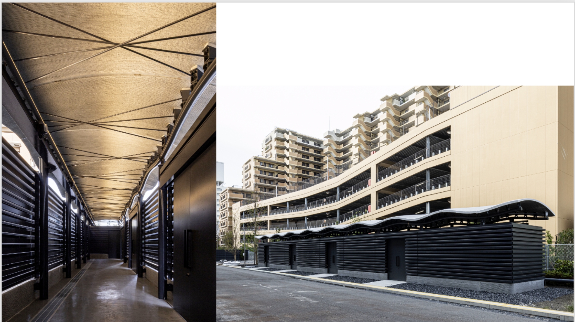
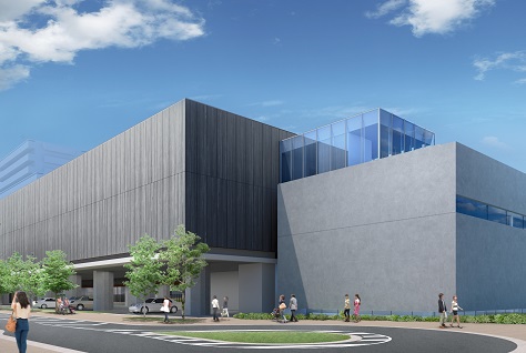
Inside the building with the lights on. Normally used as a storage unit for recyclables for Novare.
Architectural design
Takashi Kimba
Structural design
Hatsutaro Tanaka
Structural design
Miho Yamashita
Structural design
Tomoya Sugiyama
Proposing a new usage for 3D printers
The project team took a step beyond the conventional application of 3D printing in formwork and took up the challenge of using it for finishing materials and structural elements, as well as for reducing environmental impact and on-site printing construction. By leveraging digital design in their studies, the team was able to advance to the next generation of design and construction collaboration, integrating 3D printing with computer numerical control. Although this technology has only a short history of being applied to real projects, the team believes it is an effective design and construction method for a future society that demands labor savings and low environmental impact. It is well-suited for the DX era. Hopefully, this project will help promote not only the development of the technology but also its widespread social adoption, fostering a proper understanding of 3D printer technology and creating needs.