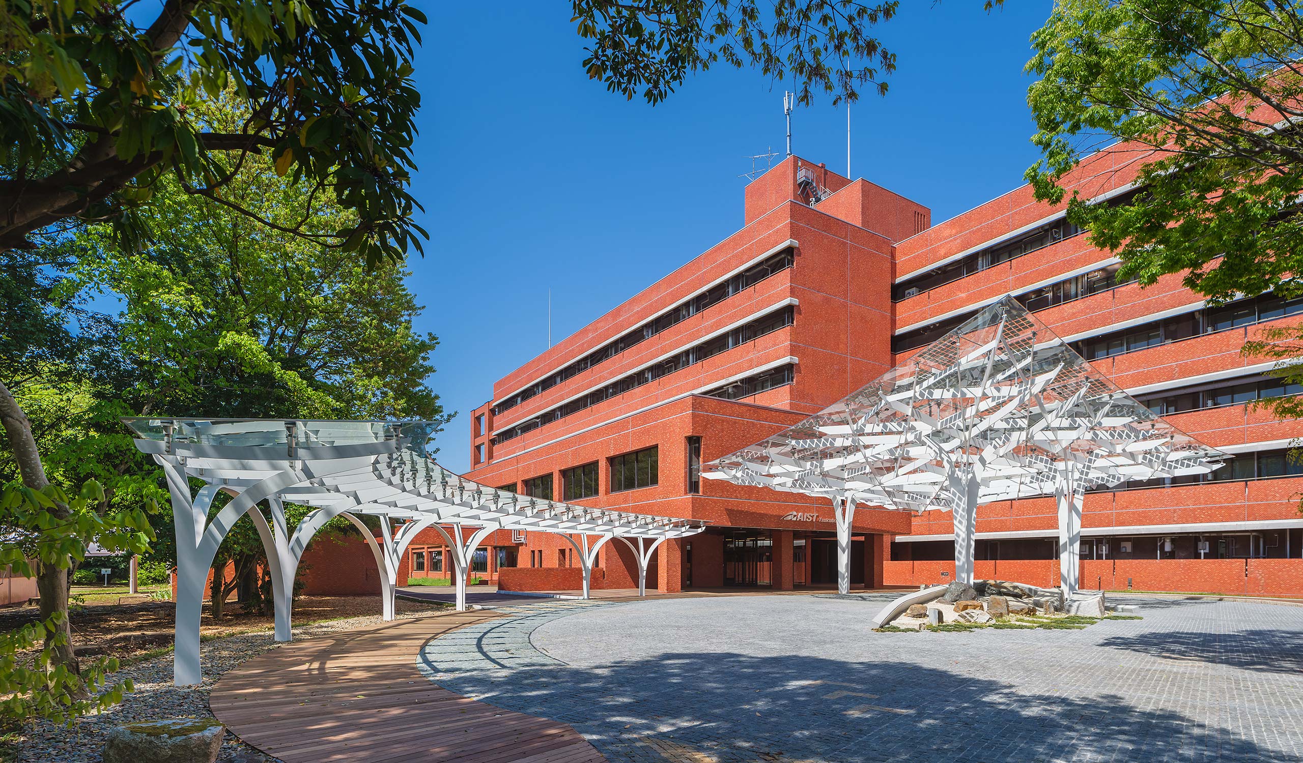
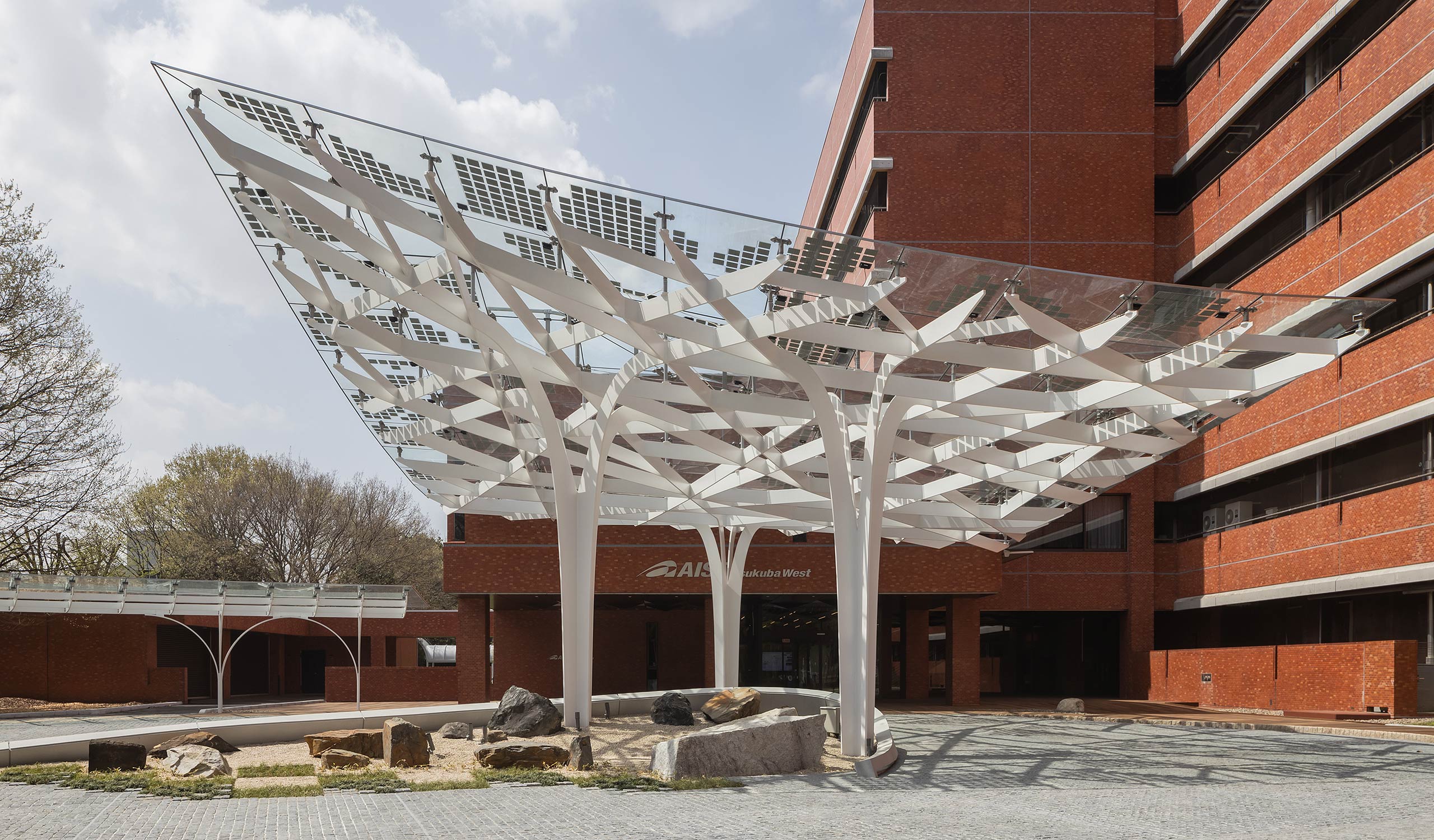
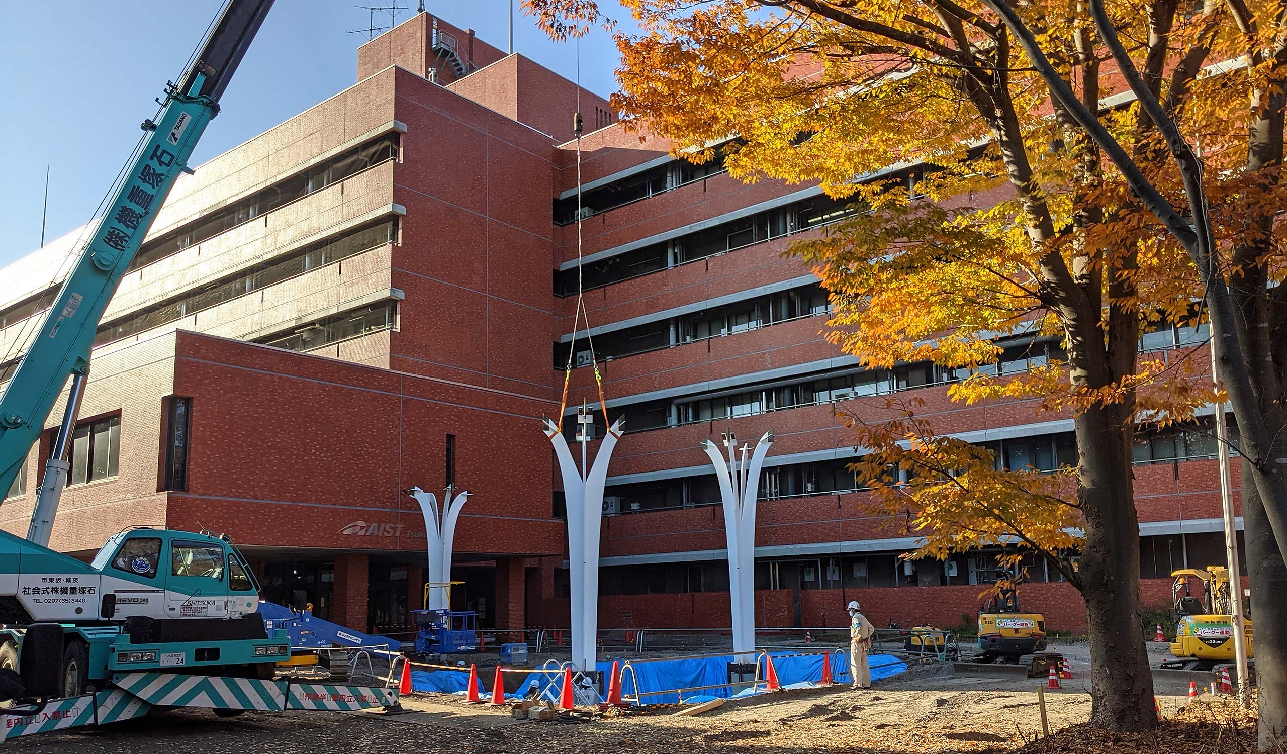
In response to the request for an iconic symbol for the world's most advanced Global Zero Emission Research Center, the "Zero-Emi Tree" was installed at the entrance of the main building as the crystallization of technology. It also functions as an awning for the passenger vehicle.
© Shinkenchikusha

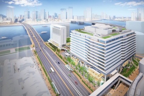
AIST GLOBAL ZERO EMISSION RESEARCH CENTER
(GZR)
The symbolic tree of a carbon-free society "Zero Emi Tree"
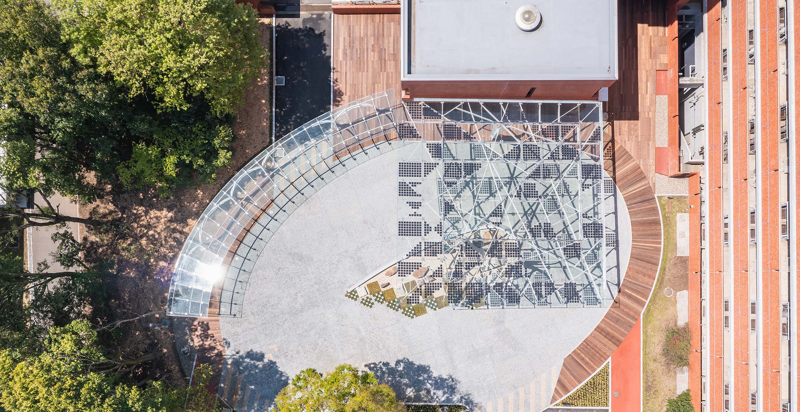
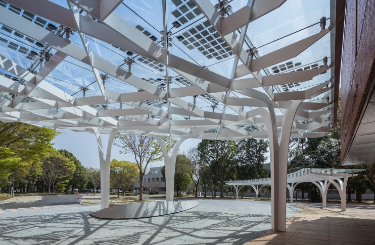
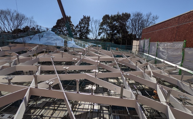
The entrance canopy for the main building has an organic branching design inspired by the fertile trees on the grounds that tell the history of AIST. We chose this motif as a symbol of the growth and development of research results and the fusion of technologies. The seamless columns and beams of flat bar steel representing the trunk and branches support the glass roof, and the tree structure with power generation cells designed to look like leaves create a bright and open space where light enters similarly to sunlight filtering through trees.
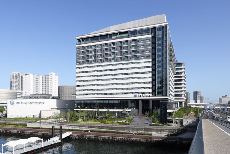
- Site
- Tsukuba City, Ibaraki Prefecture
- Site area
- 262,416.52 sqm
- Total floor area
- 473.25 sqm (new construction)
- Structure
- S structure
- Construction period
- October 2020 - March 2021 (new construction)
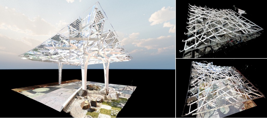
From computational design to digital fabrication
A new process of making that overlays the digital and physical in both directions
© Shinkenchikusha
Computational design
Planting digital seeds
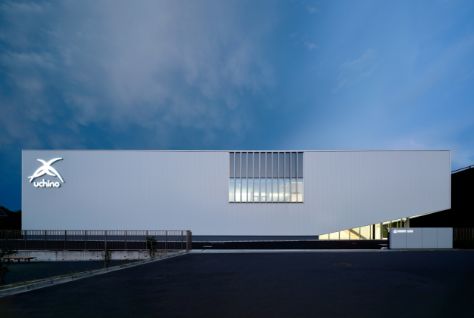
Main building around the entrance
© Shinkenchikusha
Efficient design studies that extend the possibilities of design
From the initial design stage, we used Rhinoceros + Grasshopper to algorithmize the morphogenesis of columns and beams, and created a model with the position, cross-sectional dimensions, and curvature of each member as variables. We were able to efficiently conduct a large number of design studies and explore various possibilities in a short design period. By programming the mechanism to generate a random tree shape, we were able to incorporate various conditions such as the glass support points on a 1.5m grid into the frame.
Study of how to intertwine the columns (trunks) and beams (branches)
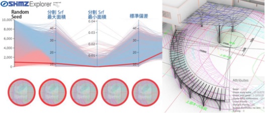
Optimization verification with Shimz Explorer, allowing for validation assessments of multiple proposals in a short time
“Zero-Emi Tree”diagram
We imagined that buds would sprout from areas avoiding vehicular traffic, the trunk and branches would grow, and it would become a large tree that welcomes visitors.
The solar power cells are scattered like leaves and light descends like sunlight filtering through the trees.
Visualizing the flow of force
A tree structure in which columns and
beams are seamlessly intertwined
© Shinkenchikusha
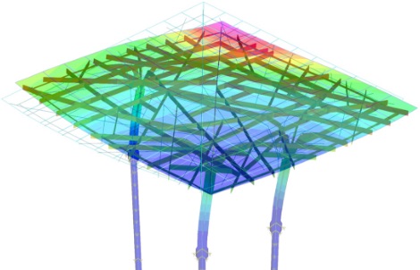
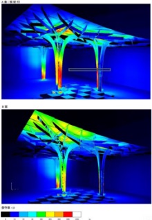
Stress analysis, structural optimization verification
After setting the positions of three columns as constraints (depending on the vehicle path), we created a parametric model in which the thickness / strength of the steel plate, the main axis direction of the columns, and the horizontal angle of the beams were set as design variables. Karamba, a structural analysis plug-in, was linked to the parametric model to build a system that can instantly check structural performance in response to changes in the structural frame shape. Additionally, we set the amount of vertical deformation and the minimization of the total steel weight as objective functions and used a genetic algorithm to search for a structural frame that satisfies these design objectives, from more than 5,000 cases.
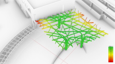
Stress analysis by Karamba
Plans and stress diagrams of the final candidates
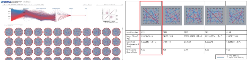
Narrowing down the optimal solution with Shimz Explorer
Seismic response analysis / glass displacement behavior analysis
To understand the effect of steel frame displacement on glass, the structural designers and façade engineers jointly created a composite model including glass and seals. This was used to perform seismic response analysis for level 2 (seismic intensity 6 and above) and displacement behavior analysis under thermal effects. Based on the analysis results, we set the glass design criteria and determined the size of the glass support brackets.
Seismic response analysis
© Production Technology Div. Facade group
Glass displacement behavior analysis
Full utilization of design model data in various simulations
Using the design model data, various performance studies were built into the design stage and performed in parallel at the same time: the analysis of rainwater paths, the impact of reflected light on existing buildings, the study of exterior lighting, the verification of brightness, etc.
Studying the impact of reflected light on existing buildings
Study of gutter details by visualizing rainwater trajectory
© Lighting M
Lighting study
© Panasonic
Brightness study
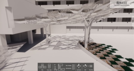
Studying the sun filtering effect using Enscape
Digital Fabrication
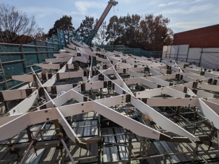
Growing a Tree
Steel frame construction view
3D Data Linking Construction
We built a program that automatically exports 2D data using Rhinoceros + Grasshopper and linked this data to the steel frame production drawings. These framework drawings were linked with the steel plate cutting data and used to create an efficient cut plan with good yield. Even when the results of the seismic response analysis called for additional changes to the members, we were able to effortlessly issue the framework drawings for these additional parts. At the factory manufacturing stage, we used the digital data to control the accuracy using the coordinate values of the machining reference points as control values.
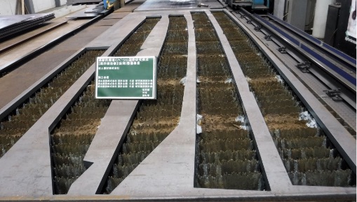
A steel plate cut by a plasma cutting machine.
Cut plate parts before assembly
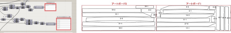
2D steel plate cutting drawings exported from the 3D model
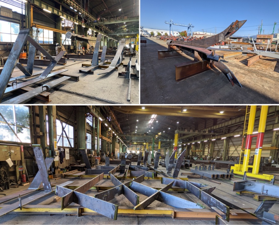
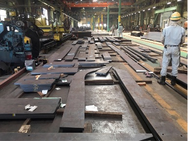
Considering transportation to the site and feasibility, we took the more than 200 pieces of cut steel plate members and assembled them into 70 units at the factory.
At the factory manufacturing stage, we used the digital data to control the accuracy using the coordinate values of the machining reference points as control values.
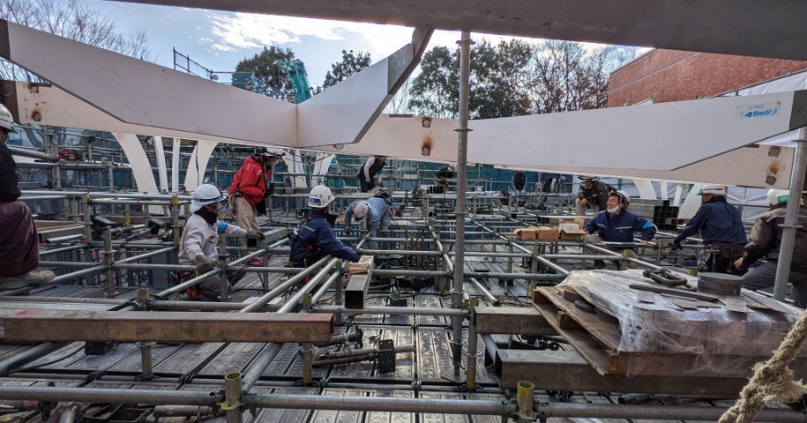
Column member steel frame construction
Beam member steel frame construction
Temporarily assemble the beam members with temporary erection pieces
Welding after temporarily assembling the entire framework
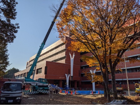
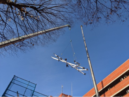
Site view: release of support points (jack-down)
Determining the jack-down procedure by construction step analysis
We performed construction step analyses at each stage of construction: temporary steel frame assembly, welding integration of the whole, jack-down, glass construction. We predicted the relationship between the welding strain, the order of release of support points, and the amount of deformation, and determined the optimum construction procedure. Coordinates for more than 121 control points were calculated from the 3D data and used for quality control.
Releasing the support points (jack-down)
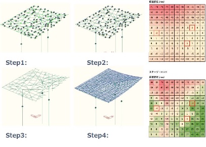
Construction step analysis
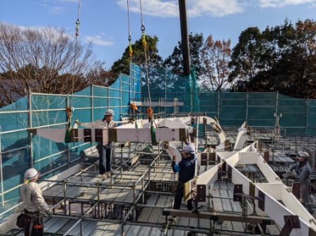
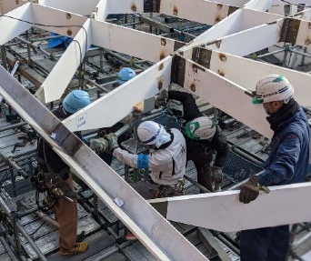
View of glass support hardware construction
Superimposing the digital and real
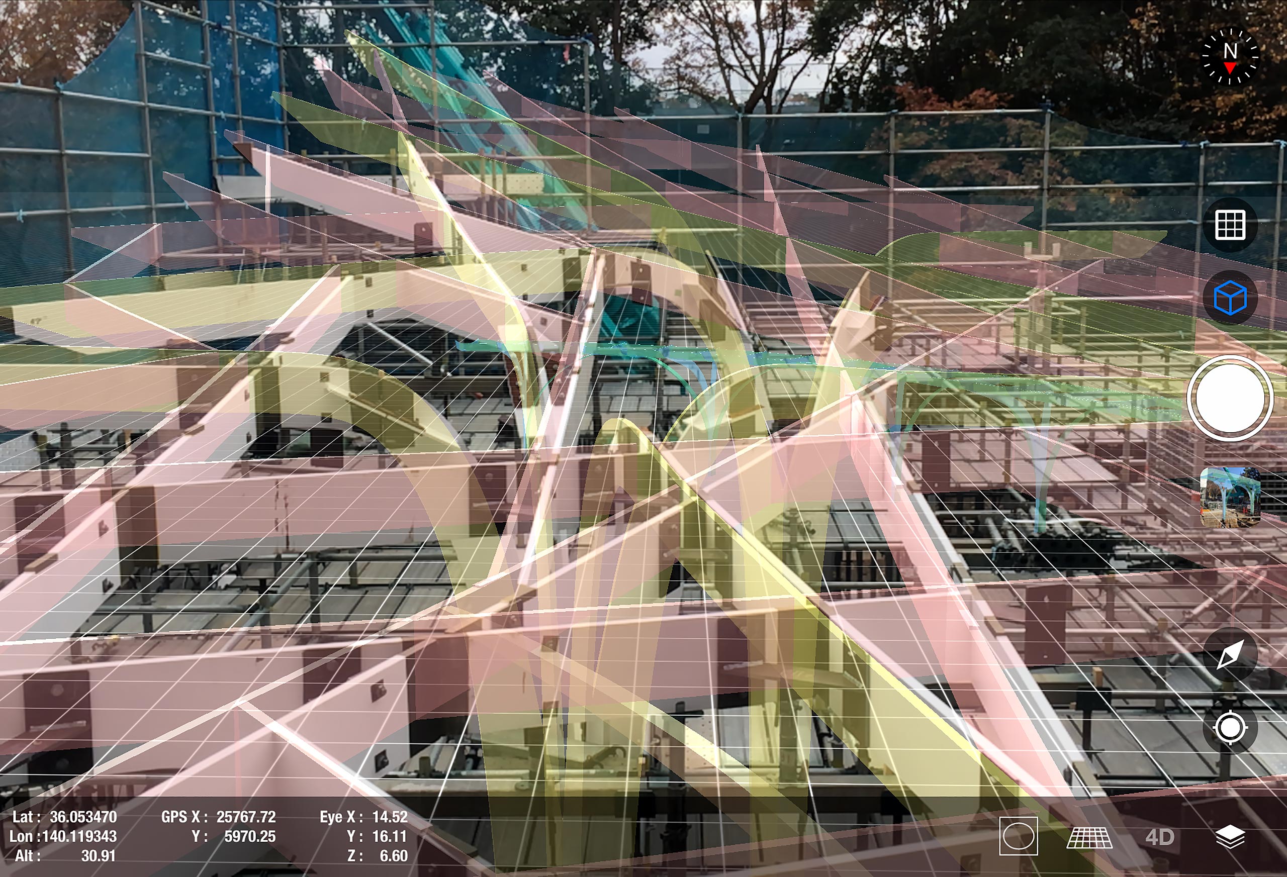
Superimposing on-site steel frame construction with the next operation in AR
Confirmation of the subsequent process using Augmented Reality
Using AR technology, we superimposed digital data onto the site. By displaying layers for each process in a complex frame, we confirmed the next process on-site and shared the completed image. (Using our app Shimz AR Eye)
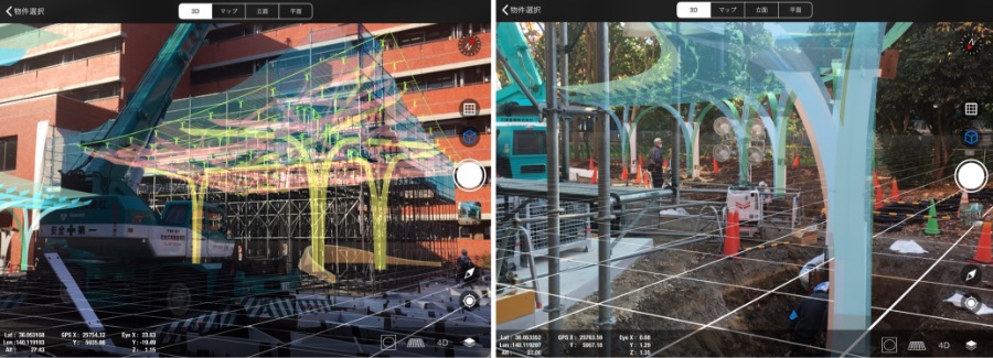
Tablet view of the site with the AR application.
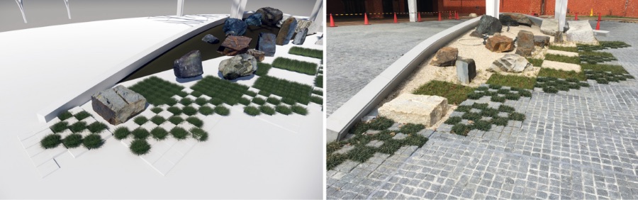
Digital mockup with 3D scanning
We performed a 3D scan of the stones to be placed on the site, and digitally studied the details of the layout using realistic mesh data including textures. This contributed to consensus-building for the completed image, facilitation of on-site work, and improved workmanship.
Quality control by 3D measurement
3D measurement of the support point was performed before and after mounting the support brackets, and high construction accuracy was achieved by superimposing the digital onto the site.
Illustrations provided by: AGC Glass Kenzai Co., Ltd. / Mitani Sangyo Co. Ltd.
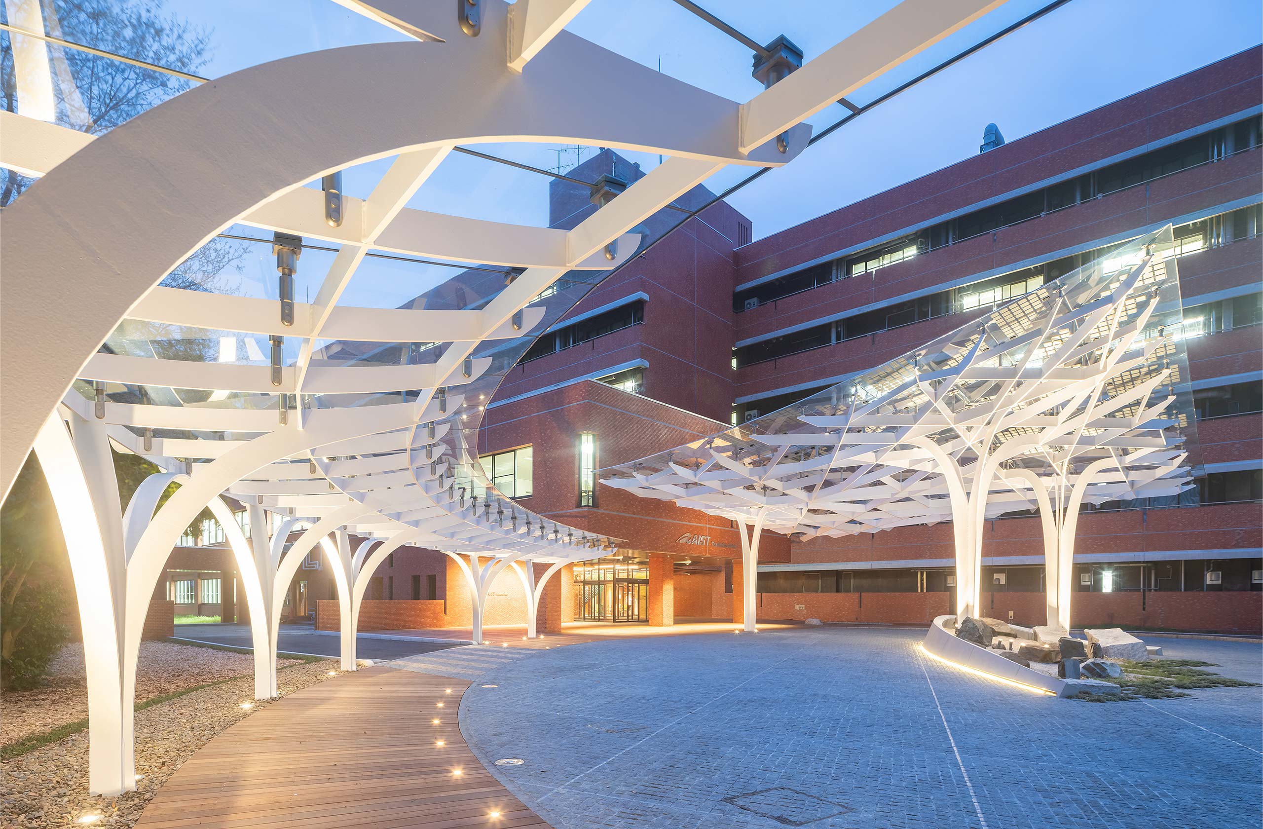
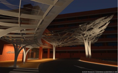
Main building vehicular approach, evening view
© Shinkenchikusha

Architectural
Design
Yasuto Tani

Architectural
Design
Shunpei Fukamachi
Structural
Design
Yushiro Hara

Structural
Design
Mitsuhiro Kuroki
Structural
Design
Satoshi Oe
The design sprouted in the digital space is nurtured into a "Zero-Emi tree" in the real space through the skills of many people. From computational design to digital fabrication, we have realized a new process of making that overlays the digital and physical spaces. The consistent use of digital products from design to construction using DDE as a platform has further potential as a solution that highly integrates design and engineering, and is a major strength for our company which is advocating for the "digital general contractor." We are confident that this will become the standard for the future