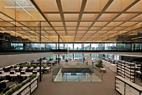
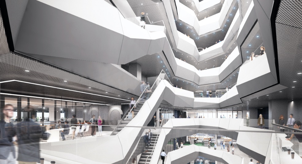
We aimed to create a building plan with a center atrium that would become the symbol of communication and collaboration. Using computational design, we explored the possibility of an active atrium that encourages collaboration between tenants and guides bright natural light to the interior.

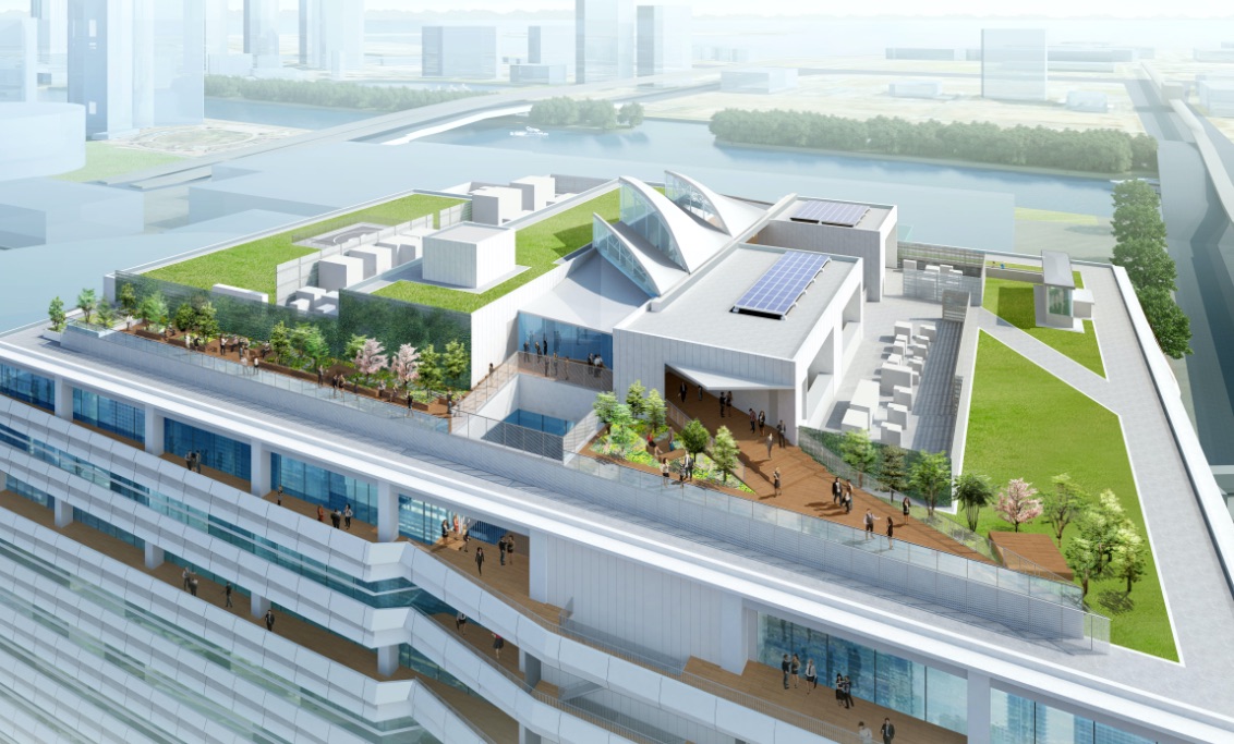
MiCHi no Terrace Toyosu
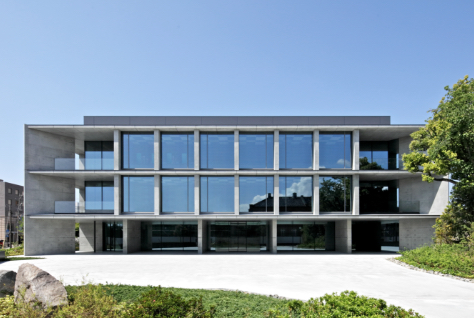
MEBKS Toyosu
Sustainable Architecture:
office space that coexists with changing needs
In continuously evolving times, the sites and functions that are required by architecture and space will change from moment to moment. This is an office building that responds to and accepts such changes. Introducing the digital design of an atrium space that illustrates "human- and environmentally-friendly architecture."
- Site
- 6-4 Toyosu, Koto-ku, Tokyo
- Total floor area
- Approx. 88,000 sqm (Office Building)
- No of floors
- 12 floors above ground
- Structure
- S structure (CFT / mid-story seismic isolation)
- Stage
- Completed (2021)
> Japan's first urban rest stop (roadside station), “Toyosu MiCHi Station”
> Tenant recruitment site
Create an Engaging
Collaboration Atrium
Using Computational Design
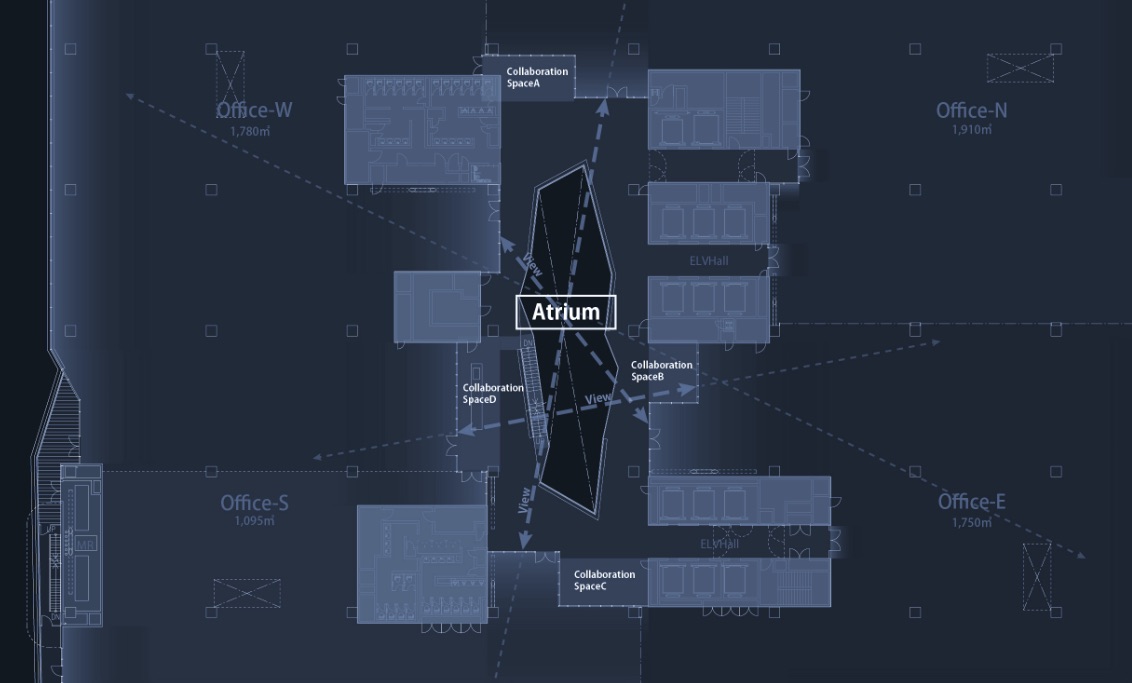
Core placement
Allowing for sight lines to
pass through
Floor plan of the central part of the building
Distributed island core allowing for sight lines transmittance
The layout is such that the sight lines can reach the edges of the workplace. We aimed to create a space that induces communication via high visibility across the atrium from anywhere in the office.
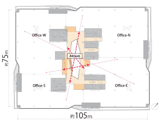
Place distributed island cores in large-scale plan offices
Study of core placement "types"
We compared the line-of-sight transmittance between tenants for the center core type and the distributed core type, which are typical for big plate offices. Comparing the line-of-sight through the central atrium, we found that the center core type has a line-of-sight transmittance of 24%, while the dispersed type has a line-of-sight of 54%. Therefore, we adopted the distributed core type for an office that encourages communication.
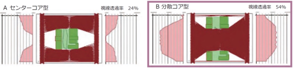
Graphing and comparing the rate of transmittance of sight lines between the center core type (left) and the distributed core type (right)
Study of core placement considering the daylighting of the workplace
When we simulated the daylight illuminance of a distributed core, the core was placed to allow for a workplace with daylight.
Therefore, one span on the outer periphery incorporates in daylight by moving the core away, reduces lighting energy, and provides a view and comfort.
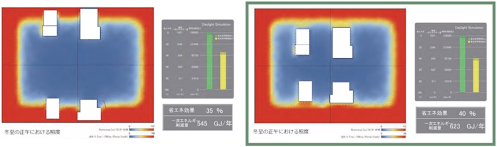
Comparison of illuminance by core placement (noon on the winter solstice)
Study of core placement considering the maximization of sight lines
In the initial distributed core type, there was a portion of the plan that became a "valley," where the tenant across the atrium could not be seen at all. Therefore, we created and studied more than 10,000 proposals using the core placement as a parameter. From those proposals, we used Shimz Explorer1 to select a core layout that allows the tenants to see each other from any angle.
1 Shimz Explorer: A tool for narrowing down2 the optimum solution using the Brute Force Method. (Developed in cooperation with: Thornton Tomasetti / CORE Studio, Algorithm Design Lab)
2 A method of narrowing down the solution by setting multiple target values from the vast number of parametrically generated possibilities.
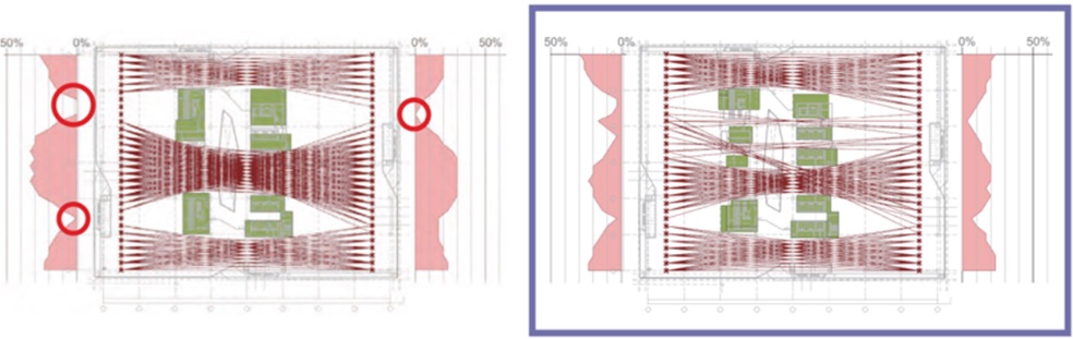
The part that becomes a "valley" where the opposite tenant cannot be seen at all (left) and the improved plan by studying the position of the core (right)
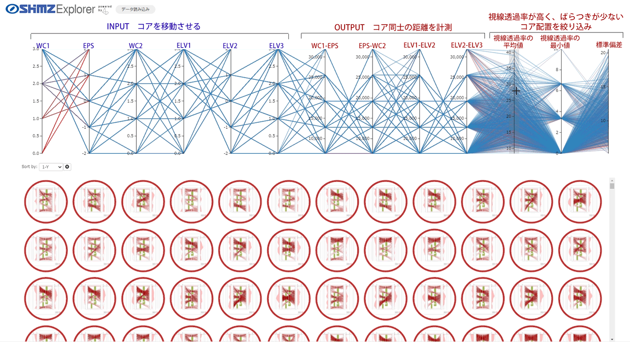
Using Shimz Explorer, narrow down the core placement that allows for the maximum sight lines
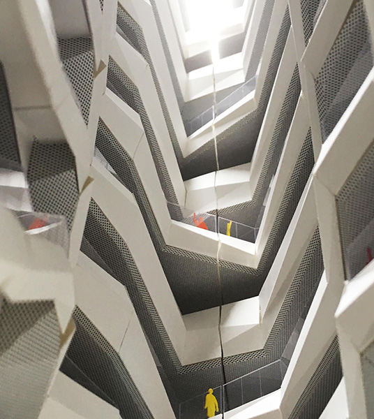
An Atrium
Guiding natural light
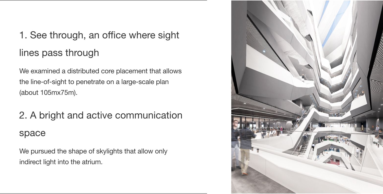
Skylight at top of the atrium
Realization of an atrium full of light
The atrium placed in the center of the plan is the key to realizing one of the concepts of this office, "WELLNESS - taking in the external environment, feeling the rhythm of light and wind, and creating a healthy work place."
We approached this atrium with a computational design to bring in natural light and create a space for communication, collaboration and relaxation.
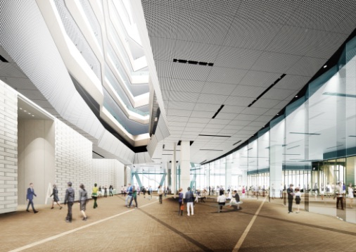
Ground floor entrance
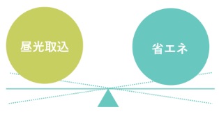
The goal is to deliver natural light to the bottom floor of the atrium. However, direct sunlight shining on the interior will increase the air conditioning load.
Therefore, we decided to use Grasshopper to find the best way to capture as much indirect light and reflected light as possible and cut off the direct light that has a large heat load.
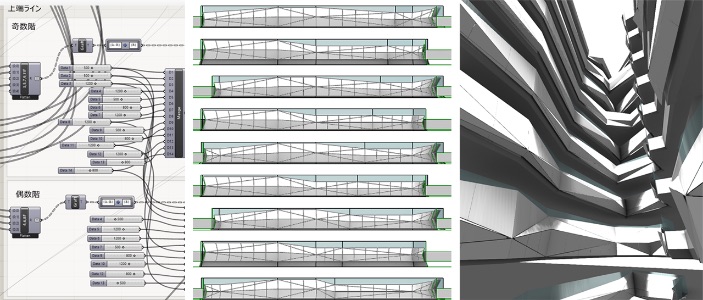
Narrow down the shape by
parameters for refinement
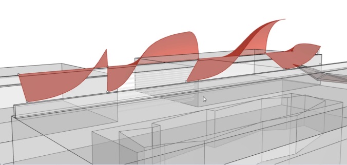
At the beginning of the study, we aimed for a skylight shape that maximizes the internal illuminance by cutting the direct light with a single curved surface. However, we soon realized that there is a limit to the internal illuminance that can be supplied with one surface.
To increase the internal illuminance, we gradually set detailed parameters for the number of openings, the height of each opening, and the ridgeline of the openings, to narrow down the shape.
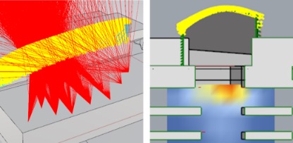
One roof surface generated to block direct light (left) and
Internal illuminance simulation on this roof (right)
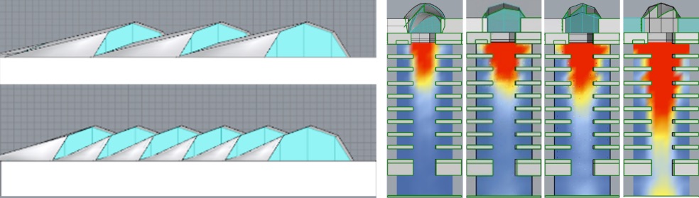
Study of the number of roofs based on internal illuminance simulation
Using assumptions from the simulation results, the heights of the peaks of the four saw-tooth roofs were set as parameters and the height of each opening was changed, and then the illuminance at the bottom of the atrium was calculated and analyzed. Based on the analysis results, we used a genetic algorithm3 to optimize more than 600 combinations and found the opening heights of the skylights that guides the most light into the atrium.
3 Genetic algorithm: One of the optimization methods that imitates the evolution of living organisms. In this project, analysis was performed using Galapagos, an optimization component that comes standard with Grasshopper.
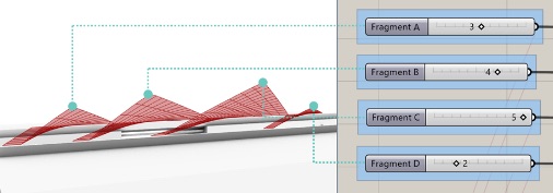
Relationship between skylight aperture height and parameters
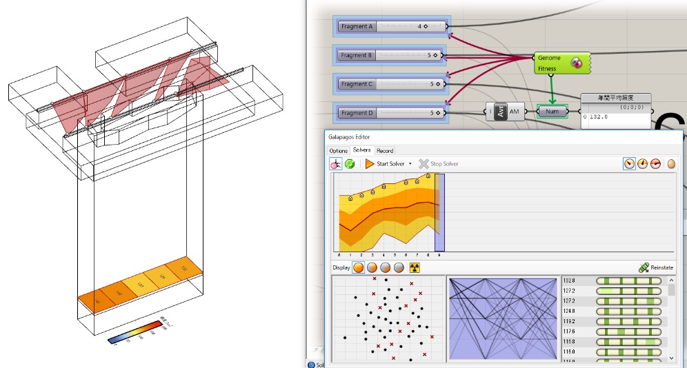
Study process of internal illuminance optimization
Next, we searched for the ridge shape of the skylight that delivered the reflected light as far down the atrium as possible. By fixing the aperture height and using the ridge shape of each surface as a parameter, we confirmed the trajectory of light falling into the atrium with a tool that visualized the destination of reflected light, that was color-coded according to the number of reflections. Based on this result, the optimization simulation was performed again, and the ideal skylight shape was derived from about 400,000 options.
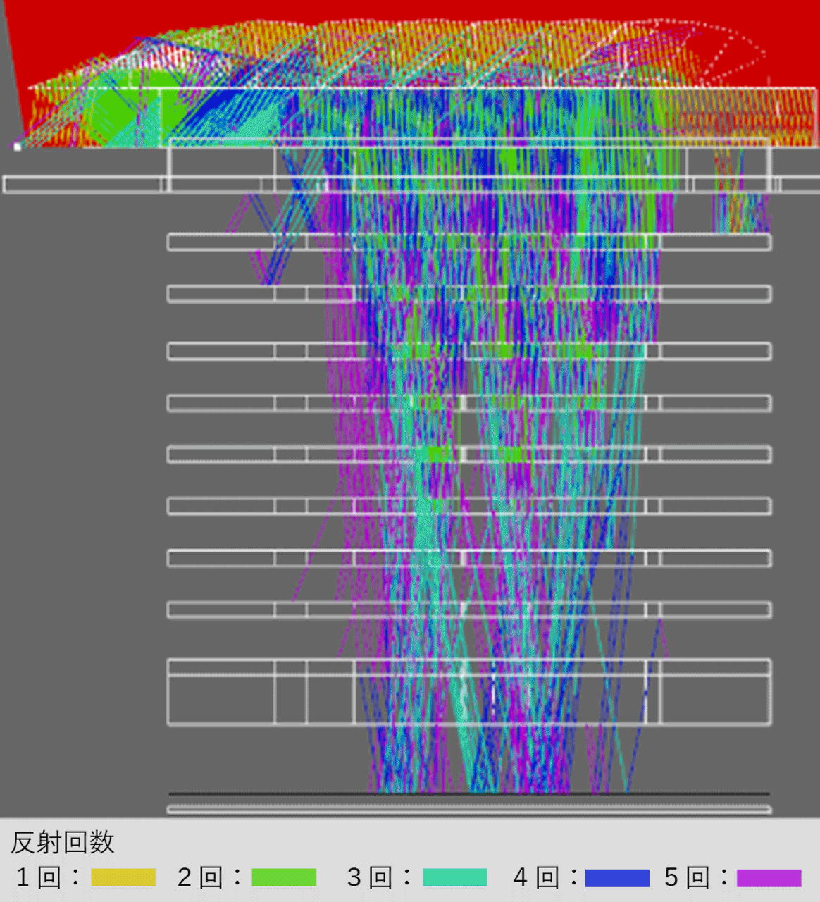
Study process of reflected light simulation
Optimal shape of the skylights
Study process of reflected light simulation
Optimal shape of the skylights
Compared to before adjusting the height and ridgeline of the opening, we were able to attain an annual average illuminance that is about twice as bright on the entrance floor, which is approximately 60m below the roof.
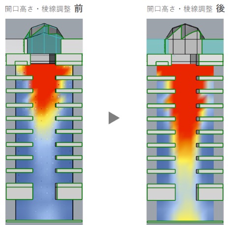
Comparison of atrium illuminance due to the difference in skylight shape
Sharing the digital data and creating the sky lights
The structure was determined by using Grasshopper to verify a rational truss arrangement with minimal members and joints, pulling from the surface data of the free-form surface. This surface was the result of the efforts to maximize the brightness of the atrium. The 3D data was then shared with the construction team and the architectural design, structural, on-site, and manufacturing4 teams collaborated on meetings, design drawings and fabrication drawings.
4 Truss verification cooperation: Tomoe Corporation; finishing material verification cooperation: Sanko Metal Industrial Co., Ltd.
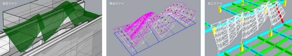
Sharing digital data (design, on-site, manufacturer)
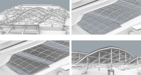
Skylight structure construction using detailed 3D model
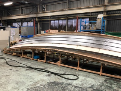
Skylight roof mock-up
Skylight structure construction using detailed 3D model
Skylight roof mock-up
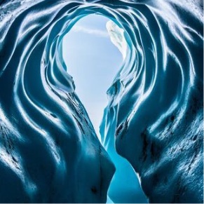
Panelization for complicated geometry
For the side panels of the atrium, we aimed for a “crevasse5”-like shape that guides the light from the skylights and reflects it towards the bottom. Therefore, the panels have a polyhedron shape, and the design was determined while adjusting the height and protrusion of the ridgeline with Rhino + Grasshopper. The data is handed over to the builder and linked to the individual detailed drawing by the manufacturer.
5 Cracks formed in glaciers, etc.
Adjust panel geometry with Grasshopper
Design study using a model
Adjust panel geometry with Grasshopper
Design study using a model
Panel geometry with prominent shadows that guide the light from the skylights
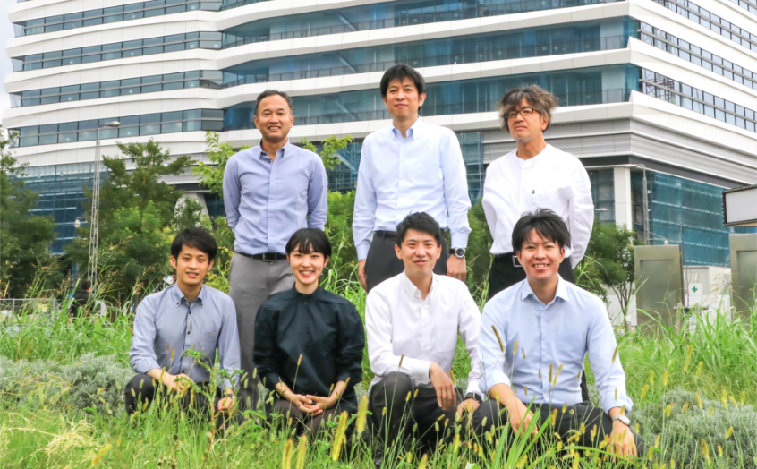
Architectural Design
Hiroshi Imai
Structural Design
Hiroyuki Kuboyama
Architectural Design
Tsuyoshi Kato
Architectural Design
Kenji Yatsu
Architectural Design
Moe Takeuchi
Architectural Design
Tomohiro Kakinaka
Structural Design
Yuya Nashimoto
By using computational design, we were able to convincingly propose non-uniform and complex designs that may at first glance seem irrational. When programming, we had a difficult time digging into "what is the problem? what should be prioritized?" and parameterizing it. Since the study process is traceable through visualization programming, we feel that it was useful for sharing with people in other fields and for collaborating with many people.
From the top left
Architectural Design Hiroshi Imai
Structural Design Hiroyuki Kuboyama
Architectural Design Tsuyoshi Kato
From the bottom left
Architectural Design Kenji Yatsu
Architectural Design Moe Takeuchi
Architectural Design Tomohiro Kakinaka
Structural Design Yuya Nashimoto
By using computational design, we were able to convincingly propose non-uniform and complex designs that may at first glance seem irrational. When programming, we had a difficult time digging into "what is the problem? what should be prioritized?" and parameterizing it. Since the study process is traceable through visualization programming, we feel that it was useful for sharing with people in other fields and for collaborating with many people.